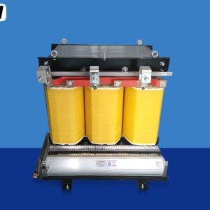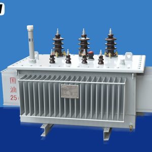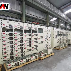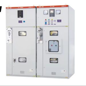
Between the distribution transformer on a pole and the grid transformer in a transmission yard sits a size range that does most of the quiet work in an industrial network: 10 to 20 MVA, with a primary at 13.8, 20 or 35 kV and a secondary that feeds a plant or a town at medium voltage. This is the point where the equipment stops being a catalogue item. Cooling moves from natural to two-stage, a tap changer becomes a mechanism rather than a link bar, impedance turns into a commercial argument because it decides how much fault current the downstream switchgear must break, and loss figures are valued in money over twenty-five years rather than accepted as a consequence of the design. A buyer at this level is not choosing a transformer; they are choosing a set of compromises and paying for them twice, once at purchase and once every hour of operation.
At a glance
| Rated power | 10 / 12.5 / 16 / 20 MVA |
| Primary voltage | 13.8 / 20 / 35 kV |
| Secondary voltage | 6.6 / 10 / 11 / 13.8 kV |
| Cooling | ONAN, ONAN / ONAF |
| Vector group | Dyn11, YNd11, YNd1 |
| Short-circuit impedance | 8 – 12 % typical |
| Tapping | OLTC plus or minus 8 x 1.25 %, or DETC |
| Frequency | 50 or 60 Hz |
| Design standards | IEC 60076-1, -2, -3, -5 |
What 10 to 20 MVA means in wire and amps
The unit of rating trips people up more often than it should. A kVA is a thousand volt-amperes and an MVA is a thousand kVA, so 20 MVA is 20 000 kVA. The number is apparent power, not useful power: a transformer is rated in volt-amperes because its limit is heating, and heating follows current, while the useful watts that come out depend on the power factor of the load. At 0.9 power factor a 20 MVA unit delivers 18 MW, and it is not being cheated of anything, because it was never sold in watts.
Current is where the size becomes physical. Twenty megavolt-amperes at 13.8 kV draws about 837 A on the primary; the same rating at 35 kV draws about 330 A. On the secondary at 13.8 kV the current is again around 837 A, and if that secondary were taken straight down to 400 V the current would be close to 29 000 A, which is why nobody does it: at that current the busbar alone would cost more than a second transformer. The 10 to 20 MVA range exists precisely to step down in two stages, keeping current and copper in a range that switchgear can handle.
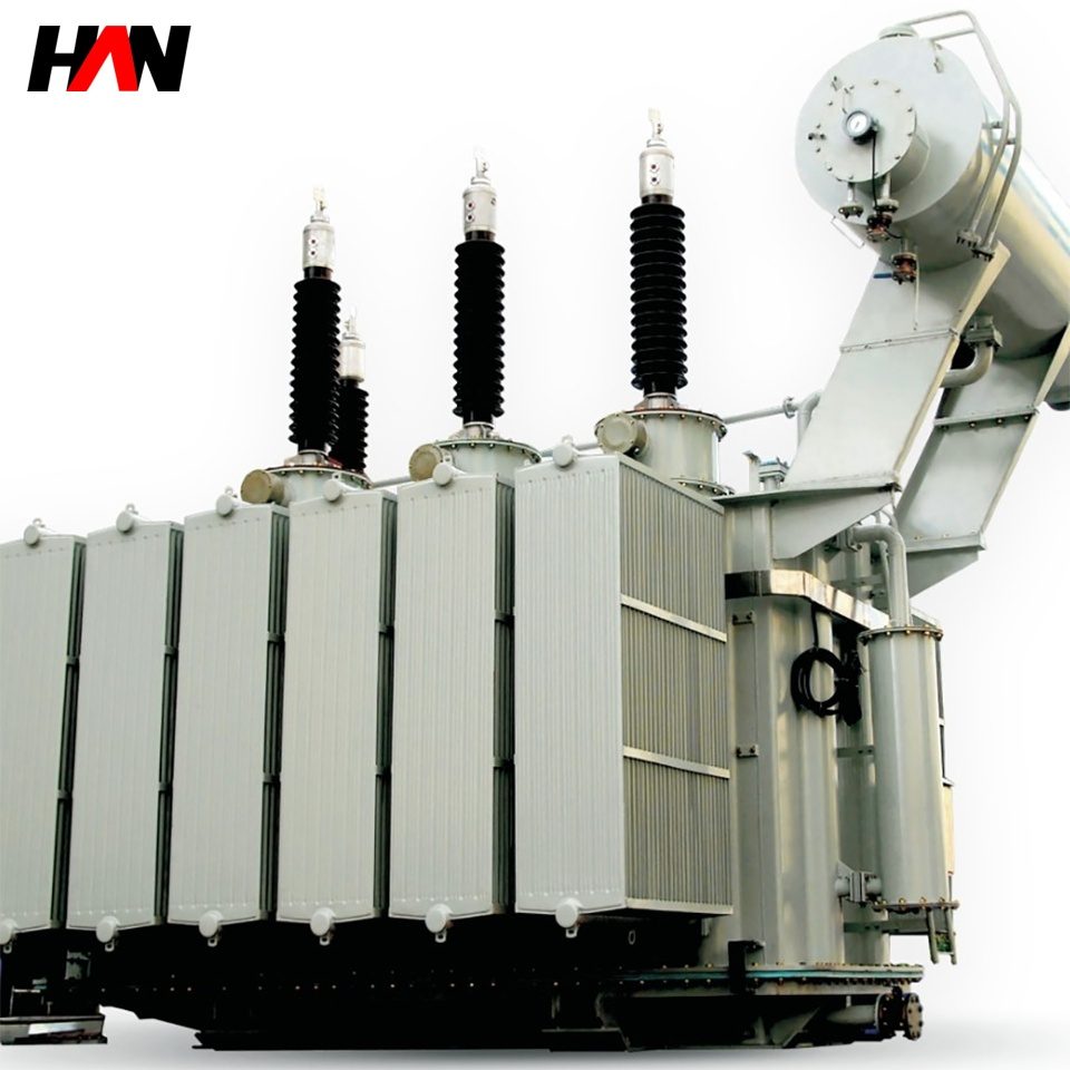
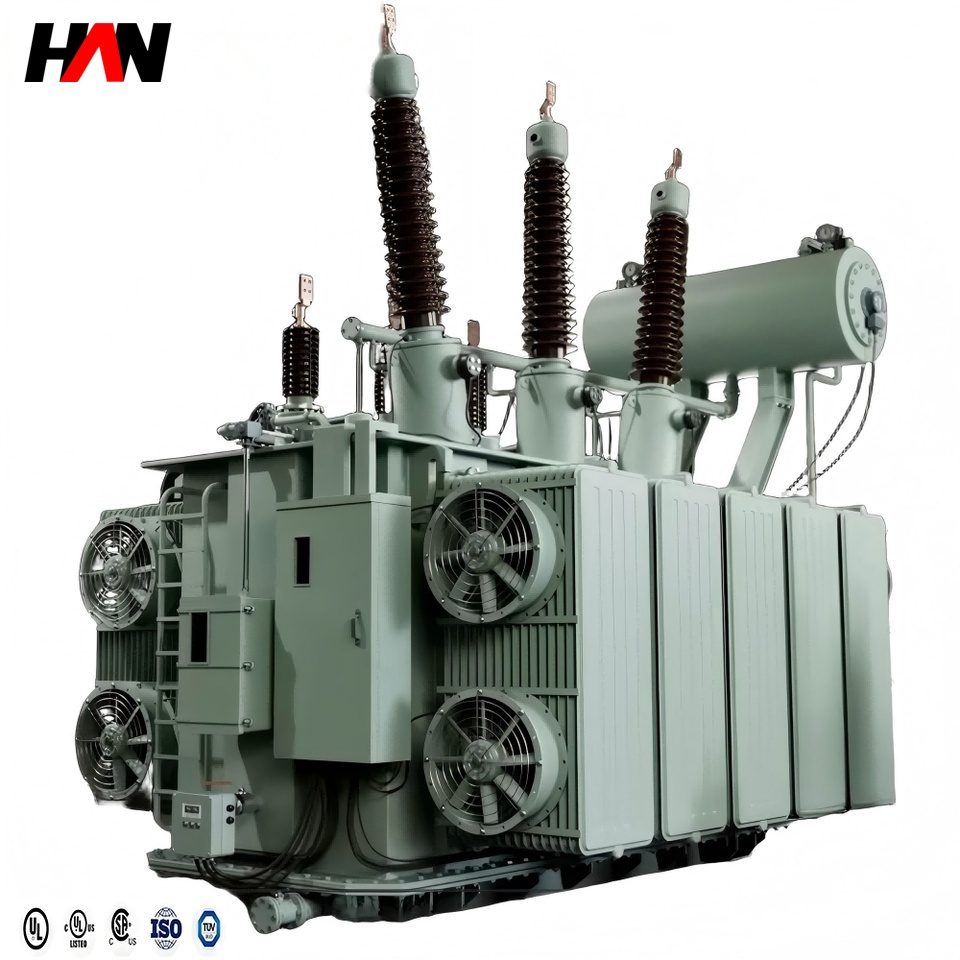
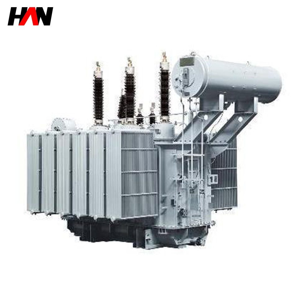
Physically the unit is a three-phase oil-immersed transformer with a corrugated or radiator tank, a conservator or a sealed design, and a core of grain-oriented steel. Ratings in this band are usually three-limb for 35 kV class and below, because a three-limb core is cheaper and shorter in magnetic path; five-limb cores appear when the unit has to fit a transport gauge or when the flux return has to be kept away from the tank wall.
Two cooling stages, and the capacity ladder they create
ONAN means oil natural, air natural: the oil circulates by convection and the tank or radiator surfaces lose heat to still air. ONAF adds fans that blow air across those radiators. Fans do not change the oil circuit; they change the rate at which heat leaves the outside of it, so the same copper and the same core can be declared at two different ratings.
A typical declaration in this size range is 12.5 MVA ONAN and 16 MVA ONAF, or 16 MVA ONAN and 20 MVA ONAF. The exact step is a design decision and must be stated on the plate, because it defines two different continuous duties. The temperature rise limits in IEC 60076-2 apply to each: roughly 60 K top-oil rise and 65 K average winding rise over the specified ambient, with the ambient reference being a 40 °C maximum and a 20 °C annual average. Fans start on winding or oil temperature and should alarm on failure, since losing them silently converts a 20 MVA unit into a 16 MVA unit that is still carrying 20 MVA.
Larger units in the range sometimes carry a third stage, ONAF with pumps, written as OFAF or OD cooling depending on whether the oil is forced through the windings or only through coolers. Each added stage buys capacity at the price of another failure mode. A pump seal that weeps, a fan motor that seizes or a cooler bank that fouls all degrade the rating without changing the load, so the protection scheme should watch winding temperature and top-oil temperature independently rather than trusting a single indicator.
Tapping: on-load against off-circuit
A transformer ratio is fixed by its turns, and the network voltage is not. Taps add or remove turns to move the ratio. How that is done separates two quite different machines.
| Criterion | On-load tap changer | Off-circuit tap changer |
|---|---|---|
| Operation | Changes tap with the unit energised and loaded | Only with the unit de-energised and locked off |
| Range | Typically plus or minus 8 steps of 1.25 % | Typically plus or minus 2 steps of 2.5 % |
| Mechanism | Tap selector plus diverter switch, resistor or reactor type | Link bar or rotary switch, no breaking duty |
| Maintenance | Contact inspection and oil care by operation count | Almost none between overhauls |
| Cost and footprint | Adds a compartment, a motor drive and a controller | Marginal |
| Best fit | Feeding a distribution network with varying voltage | Generator step-up, fixed-ratio ties, dedicated loads |
The tap changer is where the moving parts are, and moving parts under load in oil are where a transformer is most likely to fail. IEC 60214-1 governs the device: it must break the load current of the tap being left while carrying the current of the tap being taken, and it does so through a transition that briefly inserts resistance or a reactor to limit the circulating current between adjacent taps. The diverter switch does the arcing work in its own oil chamber; the tap selector does the no-current selection. That separation is why the diverter chamber has its own oil and its own maintenance interval, counted in operations rather than years.
Engineering note. Impedance is a declared value with a tolerance, not an exact property. IEC 60076-1 allows a few percent of deviation on the principal tapping, and two units of the same rating from different designs can therefore differ by enough to carry unequal shares when paralleled. That circulating current flows with no load connected, heating both units and confusing the load reading. Specify the impedance and its tolerance, and check the test certificate before paralleling a second unit.
Impedance, fault level and the voltage you actually get
Short-circuit impedance is the leakage flux between primary and secondary expressed as a percentage. It does three things at once, and they pull against each other.
- It limits fault current. The secondary fault current of a transformer is close to its rated current divided by the per-unit impedance. A 20 MVA unit at 13.8 kV rated 837 A with 10 % impedance delivers roughly 8.4 kA into a bolted fault at its terminals. Raise the impedance to 12 % and the figure falls to about 7 kA, which can be the difference between keeping a switchboard and replacing it.
- It costs reactive power. Every percent of impedance is a percent of the winding voltage lost at rated current, and the reactive component of that loss is paid for continuously. Part of it is recovered by the tap changer, part cannot be.
- It sets voltage regulation. The drop from no load to full load is roughly the resistive drop times the power factor plus the reactive drop times the sine of the load angle. At 10 % impedance and 0.85 power factor, the regulation is somewhere near 7 %, which is why the tap changer exists at all.
The design side of the same coin is short-circuit strength. A fault current produces magnetic forces between windings that rise with the square of the current, and the inner winding is pushed inward while the outer is pushed outward. IEC 60076-5 defines the duty the unit must survive: a set of short-circuit tests at reduced voltage with the current held for a specified time, after which the unit must still pass its dielectric and impedance checks. A transformer that is designed only for the thermal duty and not for the mechanical one can pass a heat calculation and still deform a winding in service.
Buying losses, not just copper
At 10 to 20 MVA the difference between a cheap core and a good one is measured in kilowatts that run for the life of the plant. The no-load loss is present whenever the unit is energised, twenty-four hours a day, whether or not anything is being produced. The load loss appears in proportion to the square of the load and peaks when the plant is busiest. Over a typical industrial load profile the no-load loss often accounts for the larger share of the annual energy bill, which is not intuitive and is the reason a loss evaluation is done at all.
The method is simple in principle. Assign a capitalised value per kilowatt of no-load loss and a lower value per kilowatt of load loss, multiply by the declared figures, and add the result to the purchase price. The values come from the local energy price and the expected years of operation, discounted. IEC 60076-20 gives efficiency levels for the same purpose from the standards side. What matters in a tender is that all bidders are asked for the same two figures at the same reference temperature, because loss figures quoted at different temperatures are not comparable.
What the factory tests prove
| Test | Class | What it demonstrates |
|---|---|---|
| Winding resistance | Routine | Joints and conductor section are as designed |
| Ratio and polarity | Routine | Turns are correct on every tap |
| Impedance and load loss | Routine | Geometry matches the design, losses match the tender |
| No-load loss and current | Routine | Core quality, joint work and insulation integrity |
| Applied and induced voltage | Routine | Main and inter-turn insulation withstand |
| Lightning impulse | Type | Withstands the BIL of the winding, turn to turn and to earth |
| Temperature rise | Type | The declared rating is thermally achievable in the tank |
| Sound level | Type or special | Meets the declared figure to IEC 60076-10 |
| Short-circuit withstand | Special or type | Winding and clamping survive the mechanical duty |
| Dissolved gas and oil tests | Routine and baseline | Clean, dry oil as a starting point for later comparison |
| Zero-sequence impedance | Special | Earth-fault current and relay settings |
| Capacitance and tan delta | Special | Bushing and winding insulation condition, and a baseline |
The distinction is not bureaucratic. Routine tests are performed on every unit and prove the individual build. Type tests are performed once on a representative design and prove the design itself, which is why a certificate for a different rating or a different winding arrangement does not cover your unit. Special tests are agreed and paid for, and they should be chosen because someone will use the result: a zero-sequence figure for the protection engineer, a tan delta baseline for the maintenance file, a sound level if there is a boundary nearby.
Where it sits in the network
The commonest arrangement is a 35 kV or 13.8 kV infeed from a subtransmission line into a primary substation, where the 10 to 20 MVA unit steps down to 13.8, 11 or 6.6 kV for a medium-voltage ring. Downstream of it sit metal-clad switchgear, distribution transformers and the low-voltage boards that actually feed loads. Upstream sit the line breaker, surge arresters, disconnectors and, in most designs, a protection relay that trips on differential current rather than on oil temperature.
The other placements are industrial. A cement line, a rolling mill, a mine hoist or a large data campus takes a 35 kV supply and steps down once at 10 to 20 MVA rather than several times at 2 MVA, because one large unit costs less per kVA and occupies less land than five small ones. Small hydro and gas engine plants use the same size as a step-up transformer, where the tap changer is usually replaced by an off-circuit link because the generator voltage is controlled at the source.
Selection and commissioning checklist
- Fix the fault level before the impedance. The switchgear downstream is bought against the transformer impedance, and changing one after the other is ordered is expensive.
- Ask for both cooling-stage ratings. ONAN and ONAF figures separately, with the fan start temperature and the alarm contact.
- Decide whether the tap changer earns its place. If the supply voltage is stable and the load is fixed, an off-circuit changer saves a mechanism, a controller and a maintenance item.
- Value the losses in the tender. Two declared loss figures at a stated reference temperature, priced with the same capitalisation factors for every bidder.
- Agree the test list in writing. Routine, type and special, with the standard edition and the acceptance criteria for each.
- Plan the transport before the foundation. Oil weight, transport weight, lifting points and the route gauge decide the tank design and the site crane.
- Set the protection on real data. Differential settings, restricted earth fault and the winding temperature trip should be calculated from the tested impedance and ratio, not from the nameplate alone.
Frequently asked questions
Is 20 MVA a large transformer?
In a factory it is the largest single unit on site. In a transmission network it is small: 230 kV transformers commonly run from 100 MVA upward. The size range matters less than the voltage, because voltage sets the insulation, the bushings and the clearances, while MVA sets the core, the copper and the cooling.
Why does the rating increase when the fans run?
Because the limit is winding temperature, and fans remove heat from the radiators faster. The copper is unchanged, so the ONAF rating is available only while the fans and their supply are healthy. That is why the two ratings are declared separately and the fans are monitored.
How often does an on-load tap changer need attention?
The interval is counted in operations and in oil condition, not in calendar years. A unit that taps several times a day and one that taps twice a year have very different maintenance needs. The manufacturer’s operation count, the diverter oil test and the contact inspection interval should all be in the maintenance plan from day one.
Does a higher impedance always reduce cost?
It can reduce the cost of the switchgear downstream by lowering the fault current, and it slightly reduces the cost of the transformer because fewer turns are needed for the same flux. It also increases reactive losses and voltage drop, and it can make parallel operation harder. The optimum is found with a study, not with a rule of thumb.
What insulation level applies at 35 kV?
For a highest voltage for equipment of 36 kV, IEC 60076-3 and IEC 60071-1 give a lightning impulse withstand of 170 kV and a power-frequency withstand of 70 kV. At 24 kV the pair is 125 kV and 50 kV, and at 12 kV it is 75 kV and 28 kV. The exact columns should be read from the standard for the declared Um.
Cooling stages, tap changer type, impedance, loss package and test list are agreed per project, so a unit in this range is designed against a load study rather than selected from a table. Send the single-line diagram, the fault level and the load profile and the specification can be closed from those three documents.