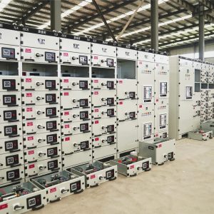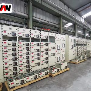
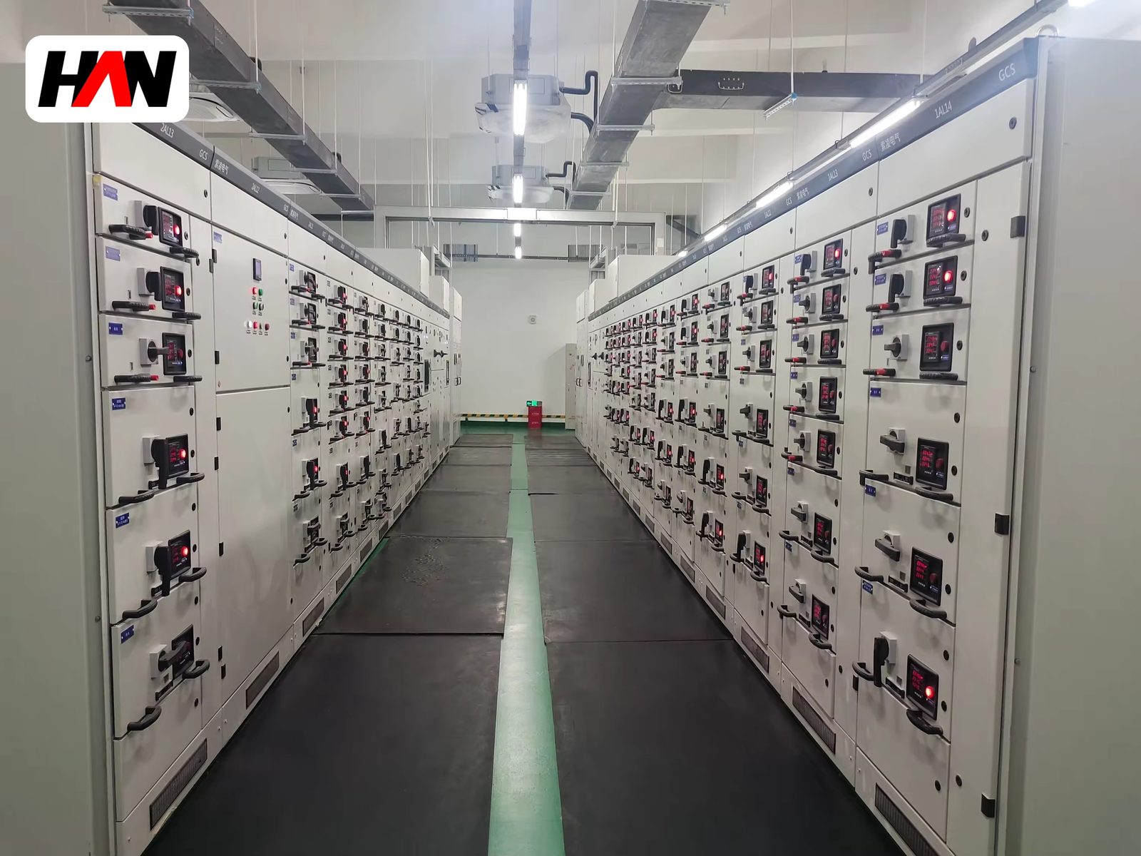
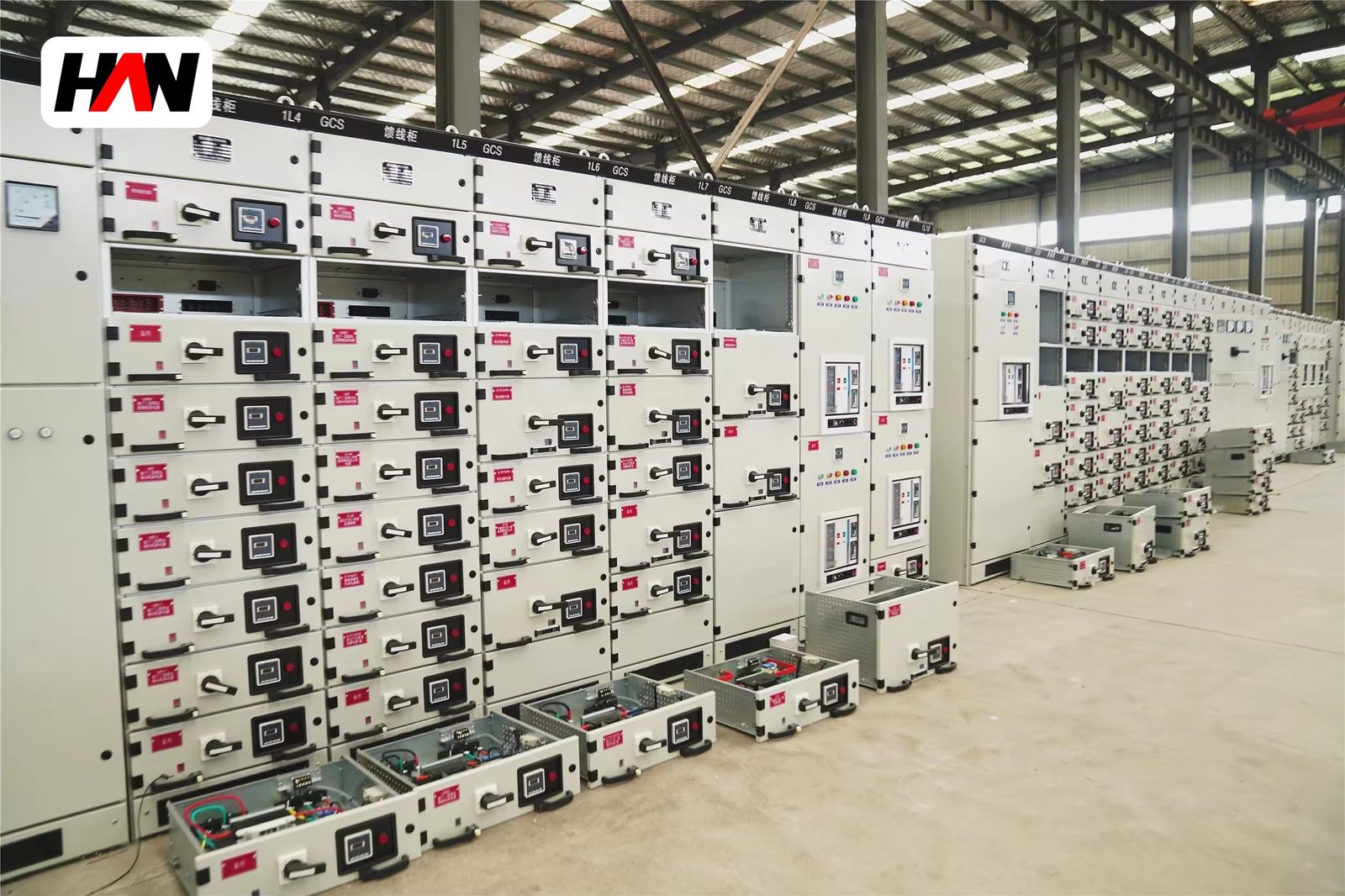
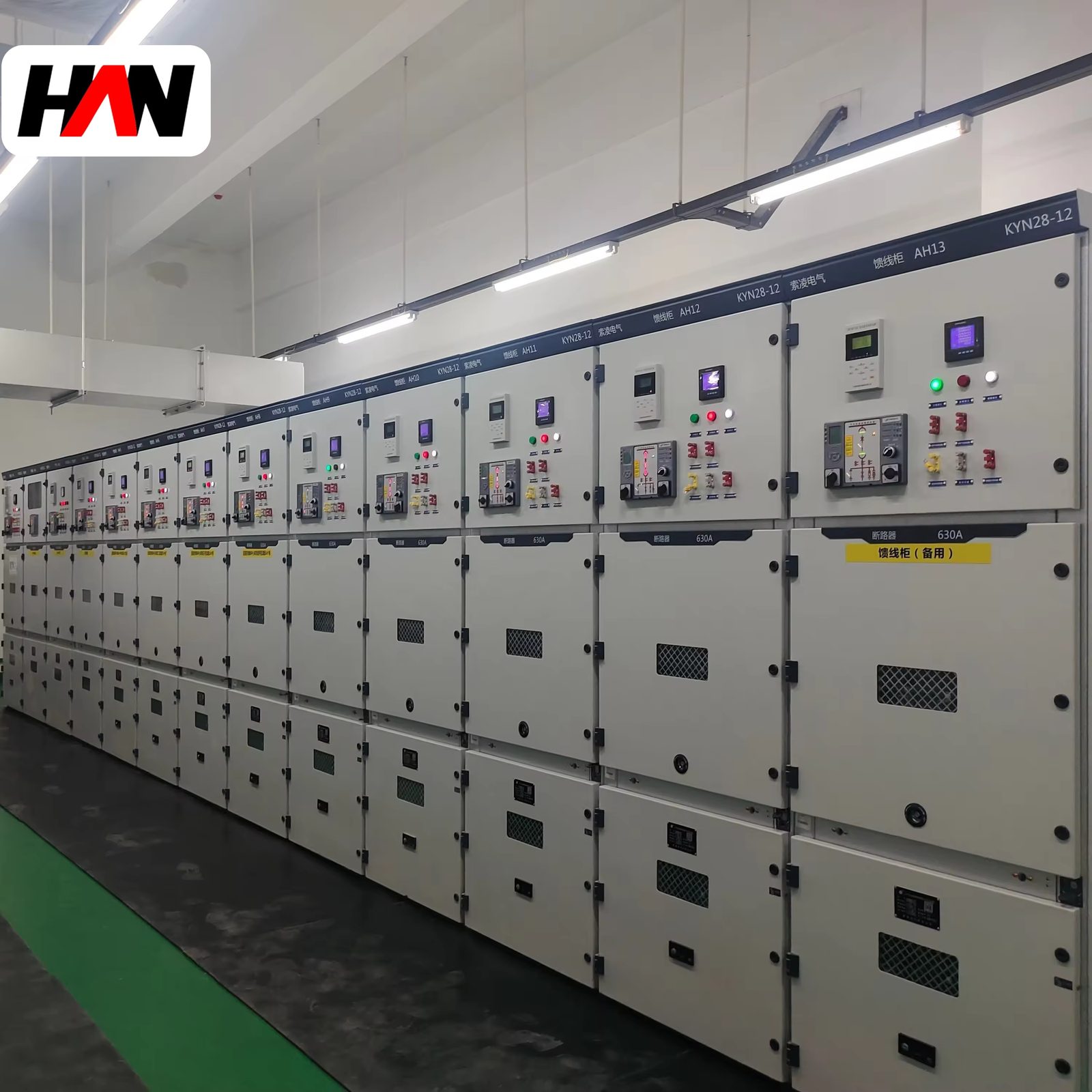
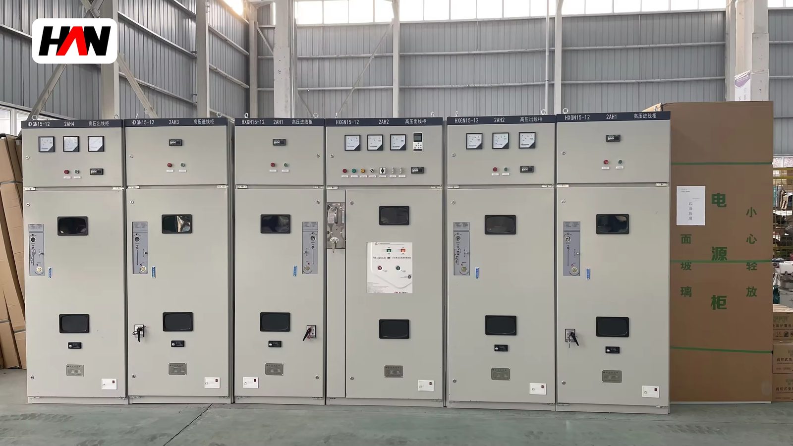
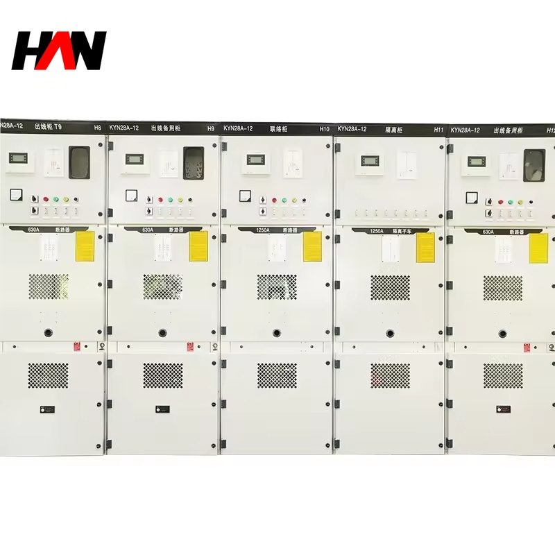
A KYN28A-12 is an indoor, metal-clad, withdrawable switchgear assembly for systems up to 12 kV. The circuit breaker rides on a handcart that racks between a service position and a test position. Busbars, breaker, cable terminations and protection relays each sit in a separate earthed steel compartment, and spring-loaded shutters close over the live contacts the moment the cart is rolled out. That single mechanical idea explains most of the cost, most of the maintenance routine and most of the safety argument behind the design.
The series spans busbar currents from 630 A to 3 150 A and short-time ratings from 20 kA to 40 kA, which covers a small industrial substation and a utility distribution board fed by a large transformer alike. It is built to IEC 62271-200 and reaches the LSC2B service-continuity class in a fully partitioned build. What follows explains what each number constrains, why the air gaps are the size they are, and where an armored assembly earns its premium over a box-type cabinet that looks identical from the front.
At a glance
| Rated voltage, Ur | 12 kV, Um 12 kV |
| Lightning impulse withstand | 75 kV peak |
| Power-frequency withstand | 28 kV, 1 min |
| Main busbar current | 630 – 3 150 A |
| Short-time withstand | 20 / 25 / 31.5 / 40 kA, 4 s |
| Interrupter type | Vacuum, withdrawable truck |
| Service continuity | LSC2B in full partition build |
| Degree of protection | IP2X internal barriers, IP4X to IP54 external |
| Design standard | IEC 62271-200, IEC 62271-100 |
What the code actually tells you
The letters are a construction code used across Chinese and export catalogues, not a performance class. The first marks the assembly as metal-clad, the second as withdrawable, the third as indoor, and the trailing number is the rated voltage in kilovolts. Two cabinets sharing the code can differ completely in fault rating, so read the code as a description of how the box is built and the rating plate for what it can do. IEC 62271-200 governs the assembly itself, replacing the older IEC 60298, and classifies it along three independent axes: partition class, loss-of-service-continuity category, and internal arc classification where one has been demonstrated.
The device inside follows IEC 62271-100, which also assigns endurance classes: E2 for extended electrical endurance and M2 for extended mechanical endurance, typically 10 000 operating cycles. Those two letters, not the kiloampere figure alone, decide how long a breaker can stay in service between interventions.
Armored against box-type: what the words buy
The distinction that matters on a specification sheet is armored against box-type, and it is entirely mechanical. In an armored assembly each main circuit sits in its own compartment, those compartments are earthed sheet steel, the busbar system has a compartment of its own, the cable terminations have one of their own, and the switching device is removable. In a box-type cabinet the breaker is bolted to a fixed frame inside one large enclosure. There may be insulating barriers, but there is no truck, no guide rail, no shutter and no separate earthed metal boundary around each circuit.
The consequence appears at maintenance time. With a truck, an operator winds the breaker down, watches the indicator move from service to test, and the shutters drop over the fixed contacts. The compartment is then dead and separated from the live busbar, so work proceeds while the rest of the board stays energised. In a box-type cabinet the same job means isolating the upstream section, because the fixed contacts are exposed once the cover comes off. A box-type design is lighter, cheaper and quicker to build, which is why it dominates compact substations where outages can be scheduled. An armored design is chosen where the plant cannot wait.
The category labels formalise this. LSC1 means opening a compartment puts the whole installation out of service, and LSC2 means the other functional units stay live. LSC2B is the highest of the three and requires a partition between every compartment of the unit, including the busbar, so each can be reached on its own terms. A cabinet claimed as LSC2B should show that arrangement in type-test documentation, not only in a brochure.
Five compartments and the path the current takes
The busbar compartment at the top carries three horizontal bars, or four with a neutral, on epoxy post insulators. Keeping it high shortens the run between sections and puts the hottest metal nearest the vents. The breaker compartment holds the truck, the rails, the earthing contact and the interlock plate that prevents the truck being moved while the breaker is closed. The cable compartment below holds current transformers, surge arresters, the earthing switch and the glands, and is deliberately the largest so a 240 mm² cable can bend without exceeding its minimum radius. A low-voltage compartment behind a hinged door carries relays, terminal blocks and control wiring, isolated from the medium-voltage side. The fifth zone is the pressure-relief duct at the top of each compartment.
Sheet thickness matters less than people expect. Frames are usually 2.0 to 2.5 mm steel, with strength coming from folded profiles rather than gauge alone. What decides survival in a fault is bar support spacing, joint quality and relief-duct geometry.
Ratings, and what each number controls
| Parameter | Typical value | What it constrains |
|---|---|---|
| Rated voltage, Ur | 12 kV | The highest system voltage the assembly may serve |
| Lightning impulse withstand | 75 kV peak | Air clearance and surge arrester duty |
| Power-frequency withstand | 28 kV, 1 min | Creepage path and pollution performance |
| Busbar normal current | 630 – 3 150 A | Transformer size the board can carry |
| Short-time withstand, Isc | 20 / 25 / 31.5 / 40 kA, 4 s | Fault level at the incoming terminals |
| Peak withstand, Ipk | 2.5 × Isc at 50 Hz | Electrodynamic force on bars and supports |
| Breaking current | 20 – 40 kA | Interrupter bottle and the arc energy it absorbs |
| Minimum air clearance | 125 mm | Compartment height and busbar pitch |
| Specific creepage, pollution degree III | 20 mm/kV | Insulator shed profile and section height |
| Ambient temperature | −5 to +40 °C | Current derating and heater sizing |
| Installation altitude | ≤ 1 000 m | Air density, hence cooling and dielectric strength |
The 75 kV impulse level deserves a pause, because it is the figure most often misquoted. It is not a voltage the cabinet meets in service. It approximates the peak of a switching surge or a nearby strike after the arresters have clipped it, applied in a laboratory as a 1.2/50 microsecond wave. The 125 mm air clearance stands in for it in a dry, clean room; a polluted room needs the creepage figure instead, because surface tracking along a dirty insulator happens at a far lower voltage than a spark through clean air.
Engineering note. Medium-voltage assemblies are often listed under IEC 60439, the old low-voltage assembly standard, or simply as high and low voltage switchgear. Neither label is a rating: IEC 60439 and its successor IEC 61439 cover assemblies whose rated voltage does not exceed 1 000 V alternating current, while a 12 kV cabinet belongs to IEC 62271-200 whatever the listing says. Check three things on the nameplate: Um of 12 kV, an impulse level of 75 kV, and a short-time current with a stated duration. A figure such as 31.5 kA without a duration cannot be checked against a fault study that assumes one second or four.
What happens under fault and heat
The first physical problem is the magnetic force between parallel bars during a short circuit. It rises with the square of instantaneous current and falls with the distance between conductors, so a 40 kA fault with a 100 kA peak produces forces an order of magnitude above anything normal load current creates. Supports are spaced so the bars flex without touching and without permanent set, and ties between phases sit where the mechanical resonance of the span is far from twice the supply frequency. A span that is quiet at 20 kA can hum and fatigue at 40 kA with the bars unchanged.
The second is heat. Resistance losses rise with the square of current and leave through the enclosure walls by convection and radiation. IEC 62271-1 fixes the reference ambient at 40 °C with a 24-hour mean of 35 °C and sets maximum conductor temperatures around 90 °C for bare copper and 105 °C for silver-plated joints, roughly a 50 to 65 K rise. A board rated 3 150 A in a 40 °C room will not carry that current at 50 °C: either the bars get wider, the vent area grows, or the rating is written down. Silver plating exists because it holds joint resistance low, and joints are where most of the heat in a well-built busbar appears.
Internal arc behaviour is the third consideration and the one most often omitted. An arc in a closed compartment raises pressure within milliseconds and throws hot gas at the vents. IEC 62271-200 defines an internal arc classification with an accessibility type and a stated arc duration, commonly 0.1 s, 0.5 s or 1 s, and the relief flap and compartment walls are designed around that duration. An assembly without a demonstrated arc test is not unsafe by definition, but it has not proved what it does when an arc occurs.
Comparing the alternatives on the same fault level
| Type | Device mounting | Where it wins | Where it costs |
|---|---|---|---|
| Armored withdrawable | Truck on rails, shutters, full partitions | Feeder restored without a bus outage | Most steel per circuit, deepest footprint |
| Box-type fixed | Bolted breaker, single enclosure | Lowest cost and shortest lead time | Busbar must be isolated for device work |
| Gas-insulated | Sealed tank, no live parts in air | Small footprint, immune to dirty air | Gas monitoring and end-of-life handling |
| Ring main unit | Three-position switch, fixed | Two-in, one-out ring node, very compact | No short-circuit breaking on ring ways |
| Fixed metal-enclosed with VCB | Bolted breaker, partitioned front | Middle ground for small substations | Slower device replacement |
The comparison is not about which type is better but about what the owner will pay for a shorter outage, on the same fault level and the same transformer.
Where it sits in a distribution chain
The arrangement starts at the medium-voltage side of a distribution transformer and runs in the opposite direction from the low-voltage board most people picture. The utility cable enters an incoming section through a load-break switch or a circuit breaker with a cable-side earthing switch, feeds a main busbar, and the busbar distributes to feeders supplying packaged substations, motor control centres or further ring nodes. Upstream sits the utility substation; downstream sits the low-voltage board, which belongs to IEC 61439 and operates at 690 V or less.
Sectors buying this class in volume share one trait: many medium-voltage feeders and no tolerance for a long bus outage. Utility distribution substations, captive power plants, water works with remote pump stations, steel and cement plants with large motor loads, airport and metro supply, and the collector side of wind and solar farms all specify armored withdrawable assemblies for that reason.
Selection and commissioning checklist
- Start from the fault level. Get the prospective short-circuit current at the point of connection, or calculate it from transformer impedance, then choose the short-time rating with margin and state the duration.
- Check the system voltage against Um. A 12 kV assembly suits systems up to 11 kV nominal. A 13.8 kV system needs the 24 kV class, even though 12 kV feels close enough.
- Fix the partition class in writing. State the service-continuity category and require the type-test report to show the same arrangement as the drawing.
- Size the cable compartment from the cable. Three-core 240 mm² at 12 kV has a bending radius that surprises people; box depth, gland plate height and earthing switch position all follow from it.
- Plan earthing before the foundation. Earthing switch, cable screen bond, frame bond and building grid meet at one point, and that cannot be fixed after the concrete is poured.
- Witness the routine tests. Power-frequency withstand per section, insulation resistance, contact resistance, and a functional check of every interlock, shutter and trip circuit.
Frequently asked questions
Is a KYN28A-12 the same as metal-clad switchgear?
In construction terms, yes. It is a metal-clad, metal-enclosed assembly to IEC 62271-200 with separate earthed compartments for busbar, withdrawable device and cable terminations, plus automatic shutters over the fixed contacts. The code is a local designation; the classification is international; both describe the same mechanical idea.
Can it be used on a 13.8 kV system?
No. Rated voltage and equipment voltage are both 12 kV, so 13.8 kV exceeds the insulation level of the assembly and its arresters. A 13.8 kV system is served by a 24 kV class assembly with a 125 kV impulse level.
Why does 3 150 A need a wider section?
Because heat leaves through the enclosure surface and the bars themselves get taller and heavier. A 1 000 mm section with 1 660 mm depth is typical above 2 000 A, against 800 mm by 1 500 mm at 1 250 A. Forced ventilation is possible but adds a maintenance item and an air path that must stay clean.
What does the test position actually do?
It separates the main contacts and closes the shutters while the secondary plug stays connected, so the breaker can be operated and its protection checked with the main circuit isolated. That is the point of the design: proof before energisation.
Does a vacuum breaker need regular servicing?
Less than the oil and air-blast designs it replaced, but not none. IEC 62271-100 assigns a mechanical endurance class, and the mechanism, auxiliary contacts, rollers and shutters each have inspection intervals.
Busbar current, short-time rating, partition class, cable entry, protection scheme and finish are all fixed per project, so a section layout follows from a single-line diagram plus the fault level and the cable schedule.