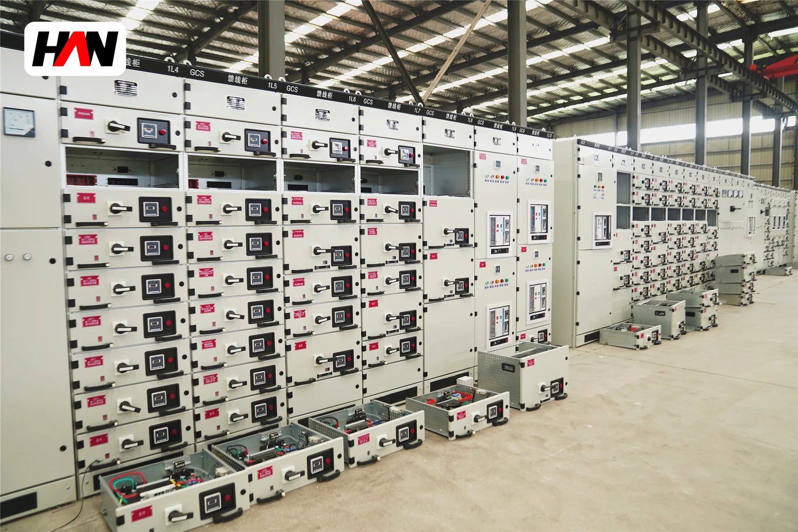
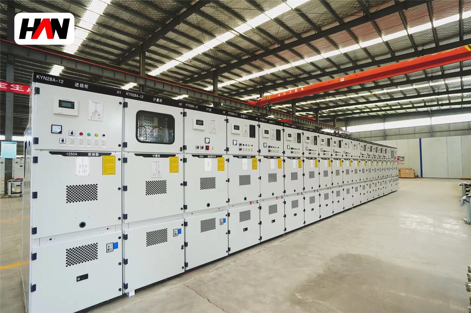
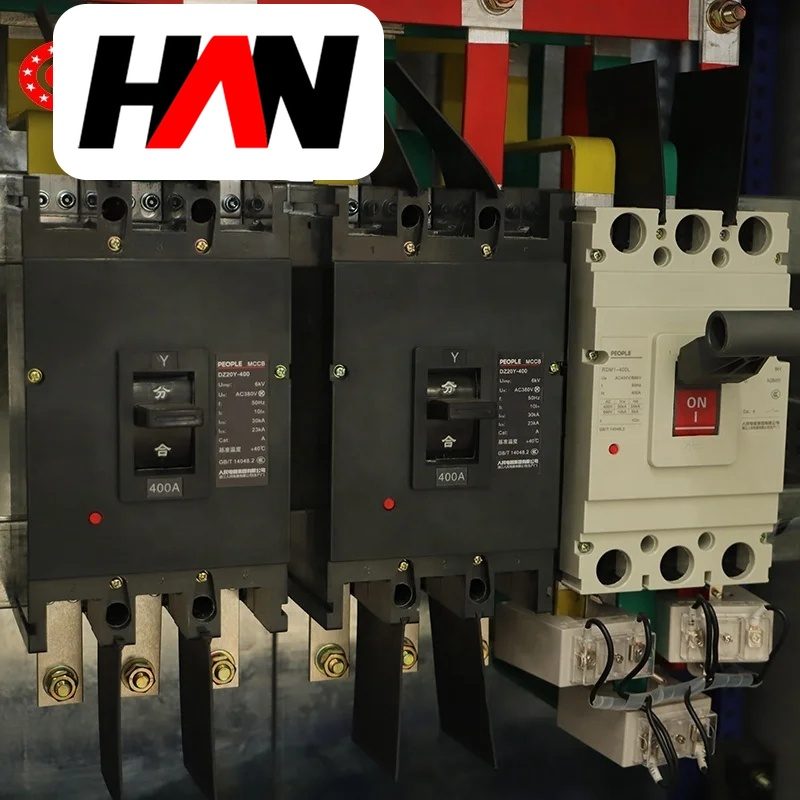
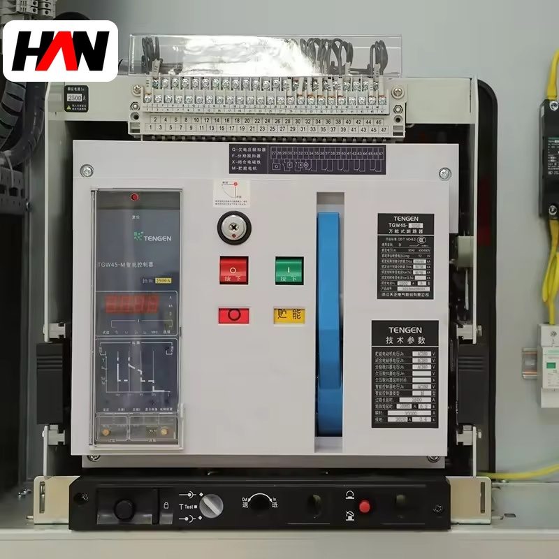
A 24 kV metal-clad assembly looks like its 12 kV sibling from across the room and differs in almost every dimension that matters. The busbars sit further apart, the compartment is taller and deeper, the insulators are longer, and the whole section weighs considerably more for the same current. None of that is styling. Every extra millimetre is there because air breaks down at a fixed field strength, and a system rated 24 kV needs roughly twice the dielectric withstand of one rated 12 kV.
This class serves nominal systems at 13.8 kV, 20 kV and 22 kV, with a lightning impulse withstand of 125 kV. The same series is built in a 36 kV insulation variant for 33 kV and 35 kV networks, which is a different rating rather than a wider version of the same one. This page explains where each number comes from, why the cabinet cannot simply be stretched to reach a higher class, and why mixing 12 kV and 24 kV sections on one busbar is not a cost saving.
At a glance
| Highest voltage for equipment, Um | 24 kV |
| Nominal systems served | 13.8 / 20 / 22 kV |
| Lightning impulse withstand | 125 kV peak |
| Power-frequency withstand | 50 kV, 1 min |
| Minimum air clearance | 180 mm |
| Busbar current | 630 – 2 500 A |
| Short-time withstand | 20 / 25 / 31.5 kA, 4 s |
| Section size, typical | 800 – 1 000 mm wide, 2 300 mm high |
| Design standard | IEC 62271-200, IEC 62271-100 |
Two voltages, and the difference between them
Documents in this market use two different voltage figures and rarely say which one they mean. IEC 60038 lists nominal system voltages, the values a network is described by: 3.3 kV, 6.6 kV, 11 kV, 22 kV and 33 kV in the metric series, alongside 13.8 kV in North American practice. IEC 62271-1 then defines Um, the highest voltage for equipment, which is a step above nominal and represents the highest steady-state voltage the insulation must tolerate. For a 20 kV network, Um is 24 kV. For a 22 kV network, it is also 24 kV.
That step exists because networks are not held at exactly nominal value. A 20 kV feeder measured at the sending end of a long line on a light-load evening can sit a few percent high, and the equipment must not be the part that fails. So the class is named after Um and the network is named after nominal, and the two numbers differ by roughly ten percent. Confusion arises when a catalogue writes the nominal value into a field labelled rated voltage. A cabinet described as 20 kV and one described as 24 kV are usually the same equipment.
The 33 kV and 35 kV entries need care. Both sit above the 24 kV class. Their equipment level is Um 36 kV with an impulse withstand of 170 kV, and a design built for 24 kV cannot be certified for them no matter what a listing claims. The physical reason is in the next section: the insulation distance that satisfies 125 kV does not satisfy 170 kV, and the difference is measured in tens of millimetres of air that the cabinet simply does not have.
Why the cabinet grows with the voltage class
Dry air breaks down at roughly 30 kV per centimetre between polished spheres in a uniform field. Real switchgear is not a pair of spheres. Bars have edges, joints have bolts, insulators have sheds, and each of those features concentrates the field, so the design stress used in practice is far below the laboratory figure. Once the working stress is fixed, clearance becomes a simple division: required withstand divided by usable stress. Doubling the withstand roughly doubles the gap.
The tabulated minimum clearances show this plainly. A 12 kV assembly needs 125 mm from phase to earth. A 24 kV assembly needs 180 mm. A 36 kV assembly needs 300 mm. Those gaps must be held in three directions at once, between phases, from phase to earth and across the open contacts of a draw-out device, and every one of them is a dimension the enclosure has to accommodate. Grow each linear dimension by a third and the volume grows by more than half. That is why a 24 kV section at the same current is deeper, heavier and more expensive, and why the extra cost is not a markup but steel and copper that had to be added.
| Insulation item | 12 kV class | 24 kV class | 36 kV class |
|---|---|---|---|
| Impulse withstand | 75 kV | 125 kV | 170 kV |
| Power-frequency withstand | 28 kV | 50 kV | 70 kV |
| Minimum air clearance | 125 mm | 180 mm | 300 mm |
| Creepage at 20 mm/kV | 240 mm | 480 mm | 720 mm |
| Typical busbar pitch | 150 – 175 mm | 210 – 230 mm | 300 – 350 mm |
| Standing height | 2 300 mm | 2 300 – 2 400 mm | 2 600 mm |
The creepage column carries a second design constraint that pure air clearance does not. A wet, polluted insulator conducts along its surface at a voltage far below what a clean air gap would hold, so the shed profile gets longer rather than the gap getting wider. At pollution degree III the reference specific creepage is 20 mm per kV of the highest phase-to-phase voltage, and heavily polluted industrial sites ask for 25 or even 31 mm per kV. On a 24 kV assembly that last figure means more than 740 mm of surface path on each support insulator, which is taller than the compartment would otherwise need. Insulation coordination is not one number but the envelope of several.
Construction and the path the current takes
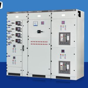
The layout follows the same five-zone pattern as any metal-clad assembly: a busbar compartment, a withdrawable breaker compartment, a cable compartment with current transformers and earthing switch, a low-voltage compartment, and a pressure-relief path out of the top. What changes at 24 kV is proportion. The busbar compartment grows because the phase pitch grows, and the cable compartment grows because the cable itself is thicker and its bending radius larger.
Designers fight the growth in three ways. Heat-shrink or epoxy-coated busbars let the phase pitch shrink back toward the clearance figure by removing the exposed air gap between bars, at the cost of a coating that must be inspected after a fault. Shaped epoxy supports replace plain cylindrical posts so that the field is graded rather than concentrated at the cap. And the compartment is arranged so the longest insulation path runs diagonally instead of straight up, which uses the depth of the section rather than its height. All three are legitimate; all three should appear in the type-test drawings rather than only in a sales drawing.
Enclosure steel is unremarkable, typically 2.0 to 2.5 mm cold-rolled sheet on a folded frame, powder coated in a light grey. The interesting materials are the insulators and the contacts. Vacuum interrupters for this class are physically longer than 12 kV bottles because the contact gap needed to withstand the recovery voltage after interruption is larger, and the ceramic envelope has to hold that gap without flashover along its outside surface.
Ratings, and what each number controls
| Parameter | Typical value | What it constrains |
|---|---|---|
| Highest voltage for equipment, Um | 24 kV | Every clearance and creepage dimension in the design |
| Lightning impulse withstand | 125 kV peak | Air clearance and arrester residual voltage |
| Power-frequency withstand | 50 kV, 1 min | The routine dielectric test and the insulator profile |
| Busbar current | 630 – 2 500 A | Transformer size and section vent area |
| Short-time withstand, Isc | 20 / 25 / 31.5 kA, 4 s | Fault level at the incoming terminals |
| Peak withstand, Ipk | 2.5 × Isc at 50 Hz | Bar supports and phase ties |
| Busbar pitch | 210 – 230 mm | Section width and the fault force between bars |
| Pollution degree | II to IV | Creepage, hence insulator height |
| Service continuity | LSC2B available | Whether a feeder can be worked on live-bus |
| Degree of protection | IP2X internal, IP41 to IP54 external | Dust and water ingress to IEC 60529 |
| Ambient temperature | −5 to +40 °C | Current derating and heater duty |
Note what the busbar pitch does to fault behaviour. Electromagnetic force between two conductors falls with the distance between them, so widening the pitch from 150 mm to 220 mm reduces the force on the bars at the same fault current. A 24 kV board is therefore, all else equal, mechanically gentler on its own busbars than a 12 kV board of the same rating. The wider pitch costs enclosure width, and it earns back support structure. This trade is one reason a 31.5 kA rating is routine at 24 kV and a much higher rating takes extra bracing at 12 kV.
Engineering note. A 12 kV section cannot be bolted onto a 24 kV busbar to save money on the outgoing feeders. The busbar joint would become the weakest dielectric point in the installation, since the clearance on one side is 180 mm and on the other 125 mm, and the joint itself adds a field concentration that neither type test covered. IEC 62271-200 certifies an assembly as a whole at a stated rating, so a mixed board has no rating at all until someone re-tests it. Where a plant needs both voltages, the correct arrangement is two boards linked by a transformer, not one board with two insulation classes.
Heat, fault current and the width of a section
Temperature rise is the quieter constraint. Copper losses rise with the square of current, and the heat leaves through the enclosure surface by convection and radiation. IEC 62271-1 sets the reference ambient at 40 °C with a 24-hour mean of 35 °C, and limits conductor temperatures to roughly 90 °C on bare copper and 105 °C on silver-plated joints. Because a 24 kV enclosure has more surface per unit of current than a 12 kV one, the same busbar current often runs cooler, which is why the current range tops out lower in the catalogue: the limit is usually the interrupter and the cable box, not the bars.
Internal arc behaviour deserves more attention at this class than at 12 kV, because the compartment volume is larger and a larger volume holds more energy before the relief flap opens. IEC 62271-200 defines the internal arc classification with an accessibility type and an arc duration, and the test is done at the rated short-time current. A 31.5 kA arc burning for half a second dissipates a substantial amount of energy inside a steel box, and the design response is a relief duct that vents away from the operator plus compartment walls thick enough not to be punctured. Any specification for a 24 kV board in a public or semi-public location should ask for that classification explicitly.
Choosing between the classes
| Criterion | 12 kV class | 24 kV class | 36 kV class |
|---|---|---|---|
| Nominal systems | 6.6 and 11 kV | 13.8, 20 and 22 kV | 33 and 35 kV |
| Section footprint | Smallest | About a third deeper | Largest, needs a wider room |
| Cost per outgoing feeder | Lowest | Middle | Highest |
| Typical fault level | 20 to 40 kA | 20 to 31.5 kA | 25 to 31.5 kA |
| Where it fits | Industrial distribution, dense plants | Utility feeders, renewables collection | Sub-transmission, large plant intakes |
A project that specifies 24 kV for an 11 kV network is buying clearance it will never use, and paying for the room to hold it. A project that specifies 12 kV for a 13.8 kV network is buying a compliance problem. The rule is mechanical: match Um to the network, not to the nearest familiar number.
Where it sits in a distribution chain
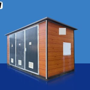
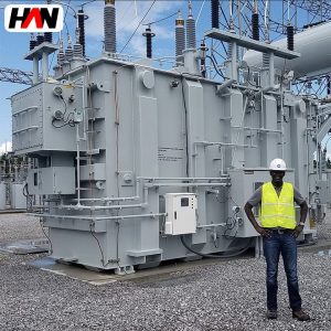
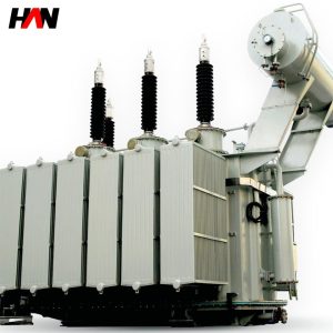
This class appears on the medium-voltage side of a 20 kV or 13.8 kV distribution transformer, in collector substations of wind and solar plants where many feeders converge at 20 or 22 kV, and in utility distribution boards that feed ring networks through cables. Downstream, the ring main units and pad-mounted transformers take over; upstream, the sub-transmission board at 36 kV or above. Between the two, this assembly is where the protection settings are decided and where the fault level is highest, because nothing inductive sits between it and the source except the transformer.
Mining, cement, water treatment and heavy fabrication also use it, usually where the site was built around a 20 kV distribution standard rather than 11 kV. Renewable projects have pushed demand upward because a 20 kV collector board carries dozens of feeders, each of which has to be isolated individually without disturbing the rest of the array.
Selection and commissioning checklist
- Confirm the network voltage and the equipment class separately. A 20 kV network maps to Um 24 kV. A 13.8 kV network also maps to Um 24 kV. A 33 kV network does not.
- Fix the pollution degree from the site, not the default. Coastal, cement-dust and fertiliser environments justify 25 mm/kV or more, and the insulator height that follows will change the section dimensions.
- Check the room before the drawing. Depth grows first at this class, and a door width that suited a 12 kV board will not pass a 24 kV section.
- Ask for the arc classification with its duration. A classification quoted without a duration and an accessibility type cannot be compared between offers.
- Verify the arrester selection against the 125 kV level. Arresters protect the assembly, but only if their residual voltage at the coordination current stays below the insulation level with margin.
- Witness the dielectric routine test. A 50 kV power-frequency test for one minute per section, plus contact resistance and a full interlock check, is the minimum evidence that the build matches the drawing.
Frequently asked questions
Can a 24 kV cabinet be used on a 13.8 kV system?
Yes, and it is the normal choice. Um 24 kV covers every nominal voltage up to 22 kV, so a 13.8 kV network is served comfortably. What is not allowed is the reverse: a 12 kV assembly on a 13.8 kV network, because 13.8 kV exceeds its equipment voltage.
Why is the impulse level 125 kV rather than a round multiple of 24?
Insulation levels are chosen from a standardised series that steps in fixed increments, so the level must clear the switching and lightning surges that protection leaves behind, with margin for ageing. The series is tabulated in IEC 62271-1 and the values are not derived from the voltage by a simple formula.
Does a wider busbar pitch mean a stronger board?
Mechanically, often yes, because the electromagnetic force between phases falls as the distance grows. Electrically it is neutral, since the clearance is set by the standard. The real cost is width, and width is what limits how many sections fit into an existing electrical room.
Can coated busbars reduce the section size?
They can reduce the phase pitch, because the exposed air gap between bars is replaced by a solid insulation layer. The trade is inspectability: after a severe fault the coating has to be checked for tracking damage, and a damaged coating is not always visible without removing the bars.
Section width, busbar current, fault rating, cable entry and pollution class are set per project, so the layout follows from the network voltage, the fault level and the cable schedule together.