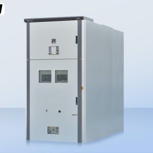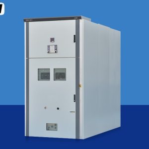
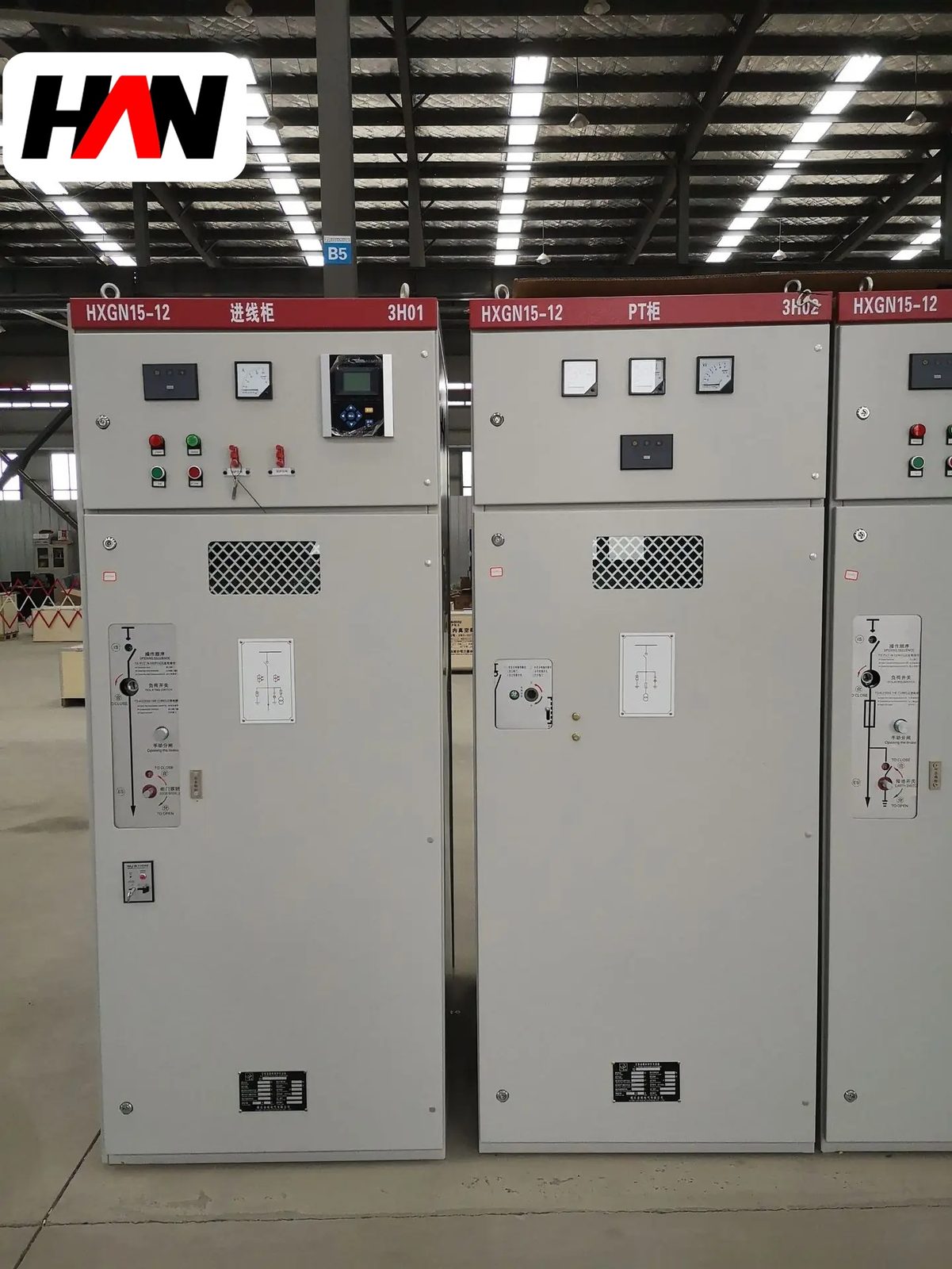
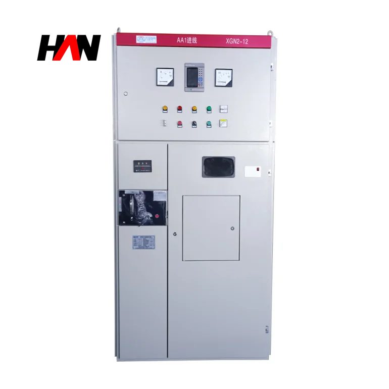
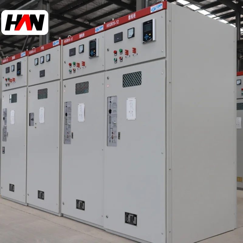
A 40.5 kV armored switchgear assembly is the point where medium voltage stops being compact. At this class the phase spacing is measured in a third of a metre, the minimum air clearance is 300 mm, each section stands about 2.6 m tall and a single transport unit can weigh over a tonne. Nothing about that is over-engineering. Air holds a fixed dielectric strength, and doubling the withstand voltage doubles the gap that has to exist in three directions inside a steel box.
This class serves 35 kV networks and the medium-voltage side of booster stations on renewable projects, with a lightning impulse withstand of 185 kV, currents from 1 250 A to 2 000 A and a short-time rating of 31.5 kA. It is withdrawable, armored and built to IEC 62271-200. This page covers what sets the geometry, how the insulation co-ordination is chosen, and where the practical limits sit when a project tries to fit a 35 kV board into a room designed for 10 kV.
At a glance
| Rated voltage, Um | 40.5 kV |
| Lightning impulse withstand | 185 kV peak |
| Power-frequency withstand | 95 kV, 1 min |
| Busbar current | 1 250 – 2 000 A |
| Short-time withstand | 31.5 kA, 4 s |
| Minimum air clearance | 300 mm |
| Phase pitch, busbars | 350 – 400 mm |
| Section size, typical | 1 400 wide, 2 800 deep, 2 600 high |
| Design standard | IEC 62271-200, IEC 62271-100 |
40.5 kV, 36 kV and 35 kV are three different things
Three numbers appear on documents for what looks like one voltage. The network is nominal 35 kV. IEC 60038 lists 33 kV as the standard nominal value for that band and 36 kV as the equipment level above it. Much of Asia, including a large installed base of 35 kV distribution, uses 40.5 kV as the equipment rating instead, one step higher again. All three describe the same job with different margins. The label on the nameplate should read 40.5 kV, and the insulation figures that go with it are an impulse level of 185 kV and a one-minute power-frequency withstand of 95 kV.
The gap between 36 kV and 40.5 kV matters when a board is compared against a specification written for the other convention. A 36 kV assembly has a 170 kV impulse level; a 40.5 kV assembly has 185 kV. The difference is small in percentage and large in hardware, because every clearance, every insulator and every busbar support has to satisfy the higher figure. When a tender mixes the two, the honest response is to ask which insulation level the fault study and the arrester selection assumed, not to quote the cheaper one.
Construction at this scale
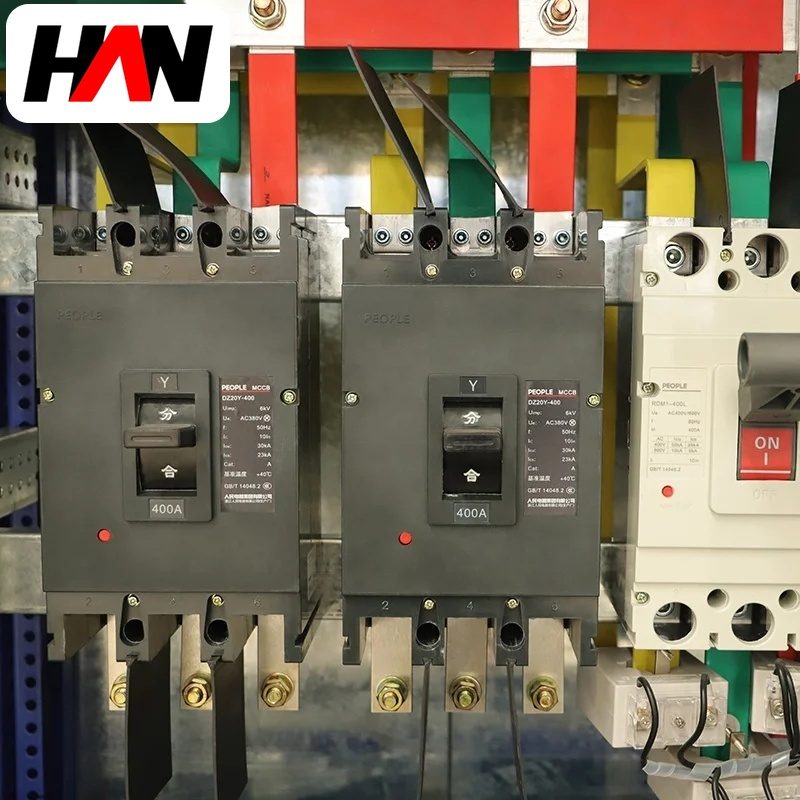
The five-zone layout is unchanged from smaller classes: busbar compartment, withdrawable breaker compartment, cable compartment with current transformers and earthing switch, low-voltage compartment, and a pressure-relief path out of the top. Scale changes how each zone is built. The busbar compartment holds three bars on epoxy post insulators tall enough to give a creepage path of about a metre, and the bars themselves are often two flat conductors per phase bolted face to face rather than one, because a single bar wide enough to carry 2 000 A would be awkward to support at this pitch.
The breaker truck carries a vacuum interrupter with a longer contact gap than a 12 kV bottle, an operating mechanism with more energy stored, and heavier primary contacts. Because the truck is heavy, it is usually moved on a rail system with a lever or a crank, and the interlock philosophy becomes more important than on a light truck: the earthing switch cannot close while the truck is in service, the truck cannot move while the breaker is closed, and the cable compartment cannot be opened while the earthing switch is open. Each of those conditions is proved by a mechanical key rather than by a label.
The cable compartment is the zone that most often catches people out. A 35 kV cable with a 400 mm² conductor has a bending radius that will not negotiate a shallow box, and three single-core cables need spacing to control sheath losses. Depth of 2 800 mm is not generous at this class; it is what remains after the busbar and breaker zones have taken their share.
Air gaps, phase spacing and creepage
Three different distances do three different jobs, and confusing them is a common specification error. Air clearance is the shortest straight-line distance through air between two live parts, or from a live part to earth, and it is what a lightning impulse has to cross. Phase spacing, sometimes called pitch, is the centre-to-centre distance between busbars of adjacent phases, which is larger than the clearance because it includes the bar width and the margin a fitter needs. Creepage is the path along the surface of an insulator, and it is what pollution degrades.
For a 40.5 kV assembly the reference air clearance is 300 mm. With a 100 mm wide bar and a practical assembly margin, the phase pitch lands between 350 and 400 mm, which is why the section is 1 400 mm wide rather than 800. Creepage at 20 mm per kV of the highest phase-to-phase voltage gives about 810 mm, and at 25 mm per kV, the level asked for in heavily polluted industrial and coastal sites, it exceeds a metre. A support insulator with a metre of surface path is roughly 400 mm tall, and that height is added to the compartment rather than shared with it.
| Distance | Typical value | What sets it |
|---|---|---|
| Air clearance, phase to earth | 300 mm | 185 kV impulse level with design margin |
| Open contact gap, withdrawable | ≥ 300 mm | Isolation distance in the test position |
| Phase pitch, busbars | 350 – 400 mm | Clearance plus bar width and assembly access |
| Creepage at 20 mm/kV | 810 mm | Pollution degree II to III |
| Creepage at 25 mm/kV | 1 010 mm | Pollution degree III to IV |
| Insulator shed height for that creepage | 400 – 450 mm | Shed profile and shed count |
The reason creepage and clearance are separate numbers is that they fail differently. A clearance failure is a spark through clean air, and it is reproducible in a laboratory. A creepage failure begins with a polluted surface becoming slightly conductive in damp weather, drawing a leakage current that dries the pollution into a track, and ends with a flashover along that track at a voltage the air gap would have held easily. That is why an assembly in a coastal plant can pass its factory dielectric test and still track in service.
Ratings, and what each number controls
| Parameter | Typical value | What it constrains |
|---|---|---|
| Highest voltage for equipment, Um | 40.5 kV | All three insulation distances |
| Lightning impulse withstand | 185 kV peak | Air clearance and arrester residual voltage |
| Power-frequency withstand | 95 kV, 1 min | Routine test level and insulator profile |
| Rated normal current | 1 250 – 2 000 A | Transformer size and bar cross-section |
| Short-time withstand, Isc | 31.5 kA, 4 s | Fault level at the incoming terminals |
| Peak withstand, Ipk | 80 kA | Bar supports and phase ties |
| Short-circuit breaking current | 31.5 kA | Interrupter bottle and arc energy |
| Section width | 1 400 mm | Phase pitch and the room the board occupies |
| Service continuity | LSC2B available | Live-bus work on a single feeder |
| Ambient temperature | −5 to +40 °C | Derating and heater duty |
The 80 kA peak figure follows from the short-time rating: IEC 62271-1 sets the peak at 2.5 times the root-mean-square value at 50 Hz, so 31.5 kA becomes 78.75 kA, rounded up to the standard 80 kA. That peak is what the bar supports actually feel. It lasts a few milliseconds, it is what bends a poorly braced busbar, and it is the reason a 2 000 A section cannot be built by widening the bars alone.
Engineering note. A 40.5 kV board is often specified for a 35 kV network that would also accept a 36 kV assembly. The two are not interchangeable in a switch room, because the 40.5 kV version needs roughly 30 mm more clearance in every direction and a taller insulator, which together push section height past 2.6 m and depth past 2.8 m. If the building already exists, the ceiling height and the door width decide the answer before the electrical comparison begins.
Fault energy at 31.5 kA
A short circuit at this class releases a different order of energy from a 12 kV fault, and the compartment has to contain it long enough for the protection to clear. IEC 62271-200 defines an internal arc classification with an accessibility type and a stated arc duration, and the assembly is tested at the rated short-time current for that duration. The design response is a relief duct that opens away from the operator, compartment walls that will not be punctured, and a cable box that will not eject a gland plate into the aisle.
Heat is the quieter constraint. IEC 62271-1 fixes the reference ambient at 40 °C with a 24-hour mean of 35 °C, and limits conductor temperatures to around 90 °C for bare copper and 105 °C for silver-plated joints. A 2 000 A busbar in a 1 400 mm wide section has enough surface to stay inside those limits at 40 °C, but not at 50 °C without derating. In a booster station where the switch room is a container in direct sun, that distinction decides whether the rating on the drawing is achievable in August.
Comparing the options at 35 kV
| Option | Footprint | Maintenance access | Best fit |
|---|---|---|---|
| Armored withdrawable, air insulated | Largest | Full live-bus access per feeder | Plant intakes, utility substations |
| Gas-insulated, sealed | Smallest | Tank access, gas handling needed | Tight rooms, harsh atmospheres |
| Fixed metal-enclosed with VCB | Medium | Bus section isolated for device work | Small substations, short feeders |
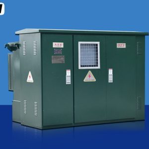
| Outdoor prefabricated enclosure | Largest, needs a pad | Walk-in, weather dependent | Sites with no switch room |
Where it fits in a distribution chain
At 35 kV this assembly usually sits on the high side of a step-down transformer feeding a plant, or as the collection board in a wind or solar booster station where several 35 kV feeders converge before the step-up transformer to 110 kV or above. Upstream of it sits the sub-transmission network and its protection; downstream sits either a 35/10 kV transformer or a 35/0.4 kV packaged substation, depending on how far the load has already been stepped down.
The renewable case explains the recent demand. A solar plant with thirty inverters feeding a 35 kV collector system needs a board with thirty feeder ways, each isolated on its own, each with its own protection settings and each able to be worked on without taking the array down. That is exactly the argument for an armored withdrawable design, and it is why this class is now specified far more often than the installed base of 35 kV industry alone would suggest.
Selection and commissioning checklist
- Settle the insulation level first. Decide whether the project follows the 36 kV convention with a 170 kV impulse level or the 40.5 kV convention with 185 kV, and write the choice into the specification.
- Measure the room before the drawing. Depth of 2 800 mm, height of 2 600 mm and a door wide enough for a 1 400 mm section decide feasibility earlier than any electrical comparison.
- Set the pollution degree from the site survey. Coastal, desert and cement-dust sites justify 25 mm/kV or more, and the insulator height that follows is not negotiable after fabrication.
- Confirm the earthing switch rating. It must withstand the same short-time current as the main circuit for the same duration, and it must be interlocked against the truck position.
- Witness the dielectric and mechanical tests. A 95 kV power-frequency test for one minute per section, contact resistance, and a full sequence check of every interlock and shutter.
Frequently asked questions
Is 40.5 kV the same as 36 kV?
No. Both are equipment ratings used for the 33 kV and 35 kV band, but 40.5 kV carries a 185 kV impulse level against 170 kV for 36 kV, and needs correspondingly larger clearances. Comparing offers without checking which convention was used leads to mismatched prices for different hardware.
Why does the phase pitch exceed the air clearance?
Because pitch is measured centre to centre and includes the bar width plus the space a fitter needs to torque a joint. Clearance is the free air distance between surfaces. A 300 mm clearance with a 100 mm bar and assembly margin lands near 380 mm pitch.
Can the board be installed outdoors?
Not as a bare indoor assembly. It needs a walk-in enclosure or a prefabricated switch room that controls temperature, humidity and solar gain, and the enclosure becomes part of the thermal design rather than a shelter bolted over the top.
Why is 2 000 A often the top of the range?
Because above that the busbar needs a cross-section and support structure that no longer fit comfortably in a 1 400 mm section, and because the interrupter and cable box become the limiting components rather than the bars. Higher currents at this voltage are usually handled by splitting the load across two transformers.
Section width, insulation level, current rating, cable entry and protection scheme are fixed per project, so the layout follows from the network voltage, the fault level and the cable schedule.