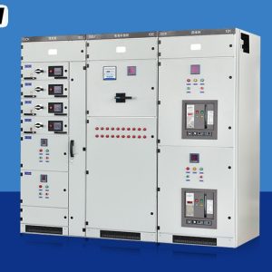
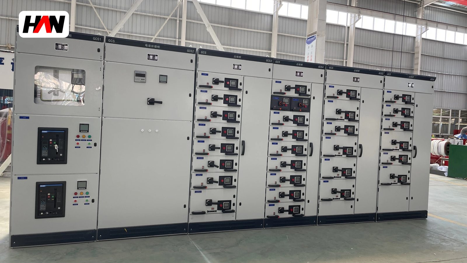
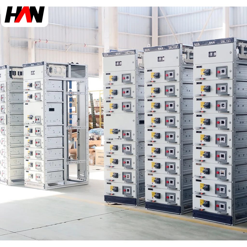
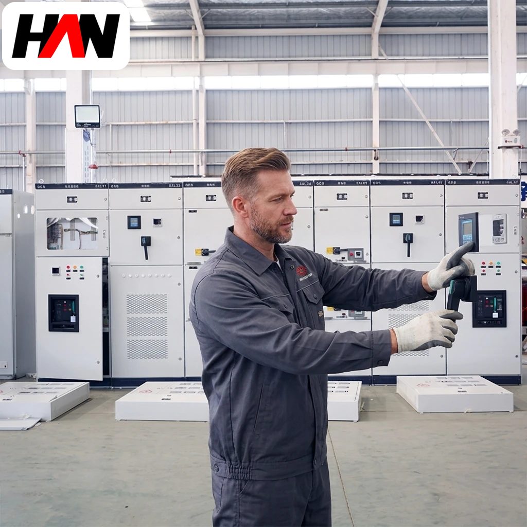
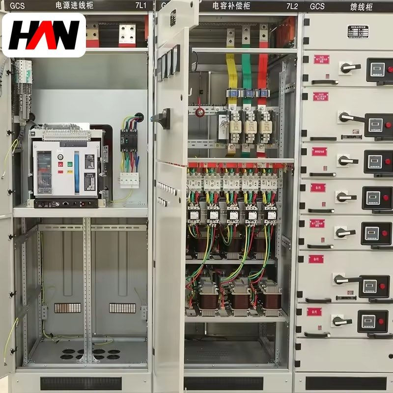
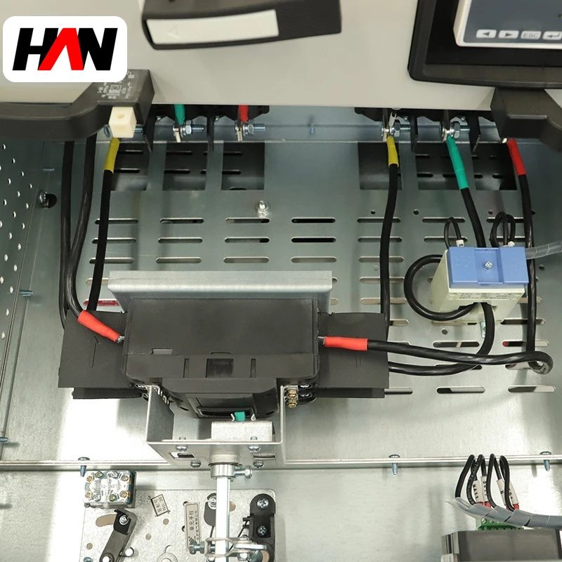
A GCS assembly is a low-voltage switchgear cabinet whose functional units slide in and out on guides instead of being bolted to a plate. Each outgoing feeder lives in its own drawer, behind its own door, and can be pulled to a test position or removed completely while the main busbar stays energised. That single mechanical idea reshapes everything else: the enclosure becomes a stack of compartments on a fixed height grid, the busbar gains a row of spring-loaded contact clusters, and maintenance turns into a swap rather than a shutdown. Plants choose it when a stopped motor costs more than the extra hardware. This page covers what the designation means, how current and fault current travel through a draw-out section, how the 8E module grid sets the layout, and where a sliding contact is the wrong engineering choice.
At a glance
| Rated operational voltage | 400 / 690 V AC |
| Main busbar current | up to 4 000 A |
| Short-time withstand, Icw | 50 kA for 1 s |
| Rated peak withstand, Ipk | 105 kA at 50 Hz |
| Drawer module heights | 8E / 16E / 24E |
| Internal separation | Form 3b or Form 4 |
| Degree of protection | IP30 – IP54 |
| Design standard | IEC 61439-1 and 61439-2 |
| Typical duty | Distribution and motor control |
What the designation identifies
GCS is a regional type code rather than a harmonised international class, so it travels badly between markets. Read it as a family name with three fixed attributes: low voltage, draw-out functional units, and a section geometry built on a vertical module grid. The code says nothing about short-circuit strength, busbar material or ingress protection; those are project variables declared in the builder’s design verification. Two cabinets carrying the same code can differ by a factor of three in fault rating.
The governing document is IEC 61439. Part 1 carries the general rules for every assembly: design verification by test or by comparison with a verified reference design, routine verification of each unit leaving the works, temperature-rise limits, short-circuit withstand, clearances and creepage distances, and the split of responsibility between the original manufacturer and the assembly builder. Part 2 adds the requirements specific to power switchgear and controlgear assemblies, which is the correct part for a cabinet full of breakers, contactors and starters.
The wording matters when a specification is written, because IEC 61439-1 fixes the vocabulary that later becomes contractual. A functional unit is the part of the assembly carrying out one function, such as feeding a pump. A transport unit is the movable carrier, the drawer itself. The forms of internal separation describe how thoroughly busbars, units and cable terminals are walled off from each other: Form 3b separates busbars and units but not their terminals, Form 4 adds terminal separation, and 4b gives each unit its own cable gland.
A section is a stack of units on a fixed grid
Look at the front of the cabinet and the pattern is regular, because the structure is modular in one direction only: vertically. The main busbars run horizontally behind a barrier at the top or in the rear, tap-offs drop into a distribution zone, and the front face is divided into cubicles whose heights are whole multiples of a base module written as E. This family uses 8E, 16E and 24E cubicles, enough granularity to hold a 63 A feeder, a 250 A moulded-case breaker or a 400 A frame without wasting space.
Each cubicle holds a drawer with a front plate, an operating mechanism and a rear carriage carrying the moving contacts. Fixed spring-loaded clusters sit on the busbar stubs behind it; as the drawer is pushed home the clusters compress and the path closes. That is why a drawer has defined positions rather than an open and closed state: connected for normal running, test where the main contacts are open but the auxiliary circuit stays live so a starter can be trialled, disconnected where the carriage is drawn back and steel shutters cover the stubs. A mechanical interlock ties the breaker to the carriage, so the breaker must be open before the drawer moves and the drawer must be seated before it closes.
Ratings, and the constraint each one places
Catalogues quote a busbar current as though it were a single honest number. In practice a handful of figures decide whether the board is usable on a given network, and they are chosen in a fixed order.
| Parameter | Typical value | What it constrains |
|---|---|---|
| Rated operational voltage, Ue | 400 / 690 V | Device selection and insulation coordination |
| Rated insulation voltage, Ui | 690 V, 1 000 V optional | Clearance and the dielectric test level |
| Main busbar current | 1 000 – 4 000 A | Transformer rating the section can take |
| Rated short-time withstand, Icw | 50 kA, 1 s | Prospective fault current at the incoming terminals |
| Rated peak withstand, Ipk | 2.1 × Icw at 50 Hz | Electrodynamic load on bars, clusters and supports |
| Rated current of a drawer | 63 – 400 A typical | Cable size, cluster rating and cubicle height |
| Utilisation category | AC-1 or AC-3, IEC 60947 | Whether the unit is a distribution feeder or a starter |
| Form of internal separation | 3b or 4 | Working on one unit with the busbar energised |
| Degree of protection | IP30 – IP54 | Dust and water ingress, classified in IEC 60529 |
| Ambient temperature | −5 to +40 °C | Permissible temperature rise and any derating |
| Installation altitude | 2 000 m without correction | Air density, hence cooling and dielectric margin |
| Section width | 600 – 1 000 mm | Unit mix per section and cable bending room |
Ue is the number the insulation system is built around. At 690 V the clearances inside a drawer have to be larger than at 400 V and the impulse withstand rises with them, so a cabinet declared for 690 V is not a 400 V cabinet with a different label. Ui sits one step above Ue and fixes the dielectric test voltage applied at routine verification. Icw is a thermal statement about bars and supports during a one-second fault; Ipk is the mechanical statement about the same hardware during the first half cycle.
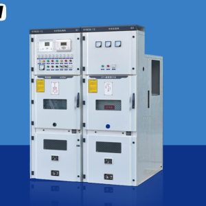
Engineering note. Draw-out low-voltage assemblies sit low on the voltage ladder, with Ue at 690 V or below. A listing that puts a GCS cabinet at 12 kV or 24 kV is attaching a medium-voltage level to a low-voltage product name; the two are different machines with different insulation, different interrupting media and a different standard, IEC 62271-200 for metal-enclosed medium-voltage switchgear. If the requirement really is 12 kV, the answer is a vacuum circuit-breaker cubicle, not a drawer.
Heat, fault current and the price of a sliding joint
Every joint has a resistance, and a contact cluster has more than a bolted lap because current crosses a set of fingers rather than solid metal. That resistance makes heat in proportion to the square of the current, and the heat must leave through the surrounding metal and air. So the busbar current of a draw-out section is limited by the temperature rise of clusters and drawer terminals, not by bar cross-section alone. IEC 61439-1 sets permissible rises above the ambient of the test, which is why a board verified at a 35 °C mean ambient cannot be assumed to carry nameplate current in a room at 50 °C.
Short-circuit forces have a different shape. Parallel conductors carrying current in opposite directions repel each other, and the force grows with the square of the instantaneous current divided by spacing. Since the peak is about 2.1 times Icw at 50 Hz, a 50 kA board is struck by something near 105 kA at the crest, and that crest is what bends supports. The moving contacts add a second concern: the cluster must stay seated under that force, which is why the carriage is latched and why cluster springs are a wear item. Internal arc behaviour, by contrast, is not a mandatory verification in IEC 61439; guidance for testing it sits in IEC/TR 61641.
What changes in daily operation
The difference from a fixed cabinet is not mainly electrical. It is procedural, and it shows up in how a maintenance team plans a working day.
| Operating aspect | Draw-out section | Fixed section |
|---|---|---|
| Restoring a failed feeder | Spare drawer inserted; terminations untouched | Device unbolted, cables disconnected and re-made |
| Isolation for work | Drawer padlocked out; one circuit affected | Upstream device opened; wider area affected |
| Spare parts holding | Few configured drawers cover many circuits | One device per circuit, no interchangeability |
| Routine maintenance | Clusters, shutters, guides and interlocks inspected | Torque checks on bolted joints, little else |
| Later expansion | Empty cubicles accept a unit in an afternoon | New section or a re-drilled plate, usually a shutdown |
That last row is why specifications ask for spare cubicles: empty space is cheap on installation day and valuable years later, when a new line needs feeders and nobody can afford a weekend outage to rebuild a busbar.
Two jobs in one enclosure
The same section serves two audiences, and mixing them is normal. On the distribution side a drawer holds a moulded-case breaker feeding a sub-board or a lighting panel, selected in category AC-1, where the load is non-inductive or lightly inductive and the unit only has to isolate and clear faults. On the motor side the drawer holds a breaker, a contactor and an overload relay or motor protection device, and the duty is AC-3, which counts starting current and the breaking of a running motor. A contactor rated 40 A in AC-1 is often a 22 A or 30 A device in AC-3 on the same frame, and that gap is where undersized starters come from.
Where the section sits in the system
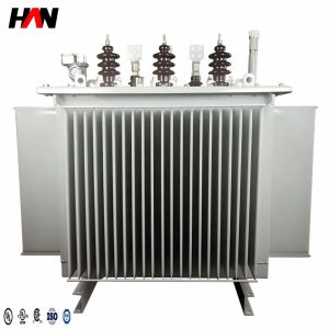
The usual chain starts at the transformer secondary, passes through a main incoming breaker and lands on the busbar of this section. From there, feeders run down to motor control centres, sub-distribution boards and final boards. Upstream, transformer impedance and utility fault level together set the kA the section will see; downstream, cable length and protection settings decide whether a fault is cleared selectively. Typical homes are process plants with continuous duty and many motors — water treatment, cement, steel finishing, pulp and paper, food processing — plus the auxiliary power systems of larger installations.
Specification and commissioning checklist
- State Icw and Ipk, not just the breaker rating. Check the declared duration, usually 1 s, against the actual clearing time of the upstream protection.
- Fix the form of separation in writing. Form 3b and Form 4 differ in whether cable terminals are compartmented, and one letter changes both price and procedure.
- Agree the unit schedule before the frame is welded. The mix of 8E, 16E and 24E cubicles sets section width and the depth needed for cable bending radius.
- Reserve spare cubicles with the busbar fitted. Space without tap-offs and shutters is a false economy; those are the parts that are hard to add later.
- Check drawer terminals against the cable. A 400 A unit taking one conductor per phase can force a lug change.
- Ask for the routine test record per section. Insulation resistance, dielectric withstand at the level for Ui, bonding continuity, and a functional check of every interlock and shutter.
Frequently asked questions
Can a drawer be changed with the busbar live?
Yes, that is the design intent, provided the form of separation and the site procedure both allow it. The unit goes to the disconnected position, shutters close over the busbar stubs, and the drawer is padlocked before removal. Separation reduces exposure but does not replace the permit.
Why does the same code come with different busbar ratings?
Because the code describes a construction family, not a performance class. Bar section, support spacing, cluster rating and declared fault level are project decisions recorded in the design verification file.
What maintenance does the mechanism need?
Cluster springs lose tension over thousands of insertions, shutters stiffen and guides collect dust. Periodic inspection with a contact-resistance check on a sample of units, a shutter operation and the specified lubricant on guides prevents most failures. Do not grease contacts.
Does draw-out construction help with arc flash?
It limits the volume a fault can pressurise and lets a faulty unit be removed quickly, but it does not by itself make the assembly arc resistant. Ask for a test to IEC/TR 61641 if that property matters.
Busbar current, fault level, unit schedule and form of separation are fixed per project, so the section layout follows from the single-line diagram and the fault study. Send both and the arrangement can be settled before fabrication starts.