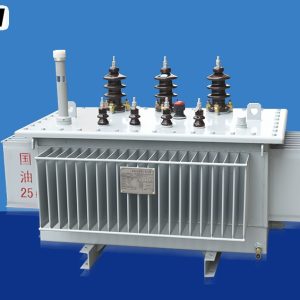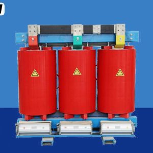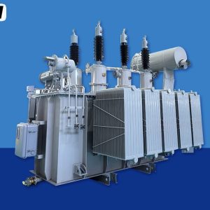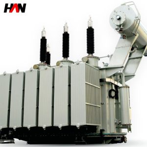
At 69 kV and above, a power transformer stops being a piece of equipment and becomes a civil, structural and logistical project with a magnetic circuit inside it. The insulation distances are no longer measured in millimetres between winding layers but in metres of air to the nearest earthed object. The tank holds tens of tonnes of oil, the bushings are porcelain or composite structures two metres tall, and the unit may travel without oil, in nitrogen, and be assembled, dried and filled on site by a crew that lives in a temporary camp for a month. Ratings in this class run from 15 MVA to 100 MVA in single units, with three-phase core-form designs dominant and voltages from 69 kV to 230 kV. What follows explains how the insulation level, the oil system and the transport gauge shape a design, and how the IEC and IEEE views of the same machine line up.
At a glance
| Rated power | 15 – 100 MVA |
| System voltage class | 69 / 115 / 138 / 161 / 230 kV |
| Highest voltage for equipment | 72.5 – 245 kV |
| Lightning impulse level | 325 – 1050 kV peak |
| Cooling | ONAN / ONAF, ODAF on larger units |
| Vector group | YNd11 standard, YNynd11 with tertiary |
| Short-circuit impedance | 10 – 14 % typical |
| Tapping | OLTC on the HV winding, or DETC |
| Design standards | IEC 60076-1 to -5, IEEE C57.12.00 |
What the voltage class changes about the machine
Power rating decides how much iron and copper is needed. Voltage class decides almost everything else. At 72.5 kV the phase-to-phase clearance inside a tank is a few hundred millimetres and the winding insulation is a matter of paper thickness and oil ducts. At 245 kV the same clearance is over a metre in air, the winding end insulation is a shaped structure with its own electric field plot, and the tank is a pressure vessel whose walls must resist a sudden internal arc without rupturing.
The reason is straightforward. Air breaks down at roughly 3 kV per millimetre in a uniform field, but almost no practical electrode arrangement is uniform, so the average stress a design can use is a small fraction of that figure and falls further as the gap grows. Oil is about three times better than air, and oil-impregnated paper better still, which is why high-voltage windings are immersed: the insulation lives in a solid-liquid composite where the oil fills the voids and the paper carries the stress.
Insulation level, BIL, and the wave behind the number
The basic lightning impulse insulation level, almost always written BIL or LIWL, is a peak voltage the winding must withstand when struck by a standard lightning impulse: a wave that rises to its peak in 1.2 microseconds and falls to half that value in 50 microseconds. The test is not a gentle ramp. It is a fast front that distributes voltage unevenly across the winding, with most of the stress appearing across the first few discs, which is why the end turns of a high-voltage winding carry extra insulation and why interleaved or shielded winding sections exist at all.
Two other dielectric duties sit beside it. The power-frequency withstand proves the insulation can hold normal and temporarily elevated voltage for a minute. For equipment with a highest voltage above roughly 300 kV, a switching impulse test is added, because slow front surges from line energisation and fault clearing become the governing stress at those levels. Below that, the lightning impulse governs, and the switching impulse test is not normally specified.
| IEEE class | BIL, kV peak | IEC Um, kV | IEC impulse / AC, kV |
|---|---|---|---|
| 69 kV | 350 | 72.5 | 325 / 140 |
| 115 kV | 550 | 123 | 550 / 230 |
| 138 kV | 650 | 145 | 650 / 275 |
| 161 kV | 750 | 170 | 750 / 325 |
| 230 kV | 825 / 900 / 1050 | 245 | 1050 / 460 |
The two families do not use the same reference, which is the source of most confusion in cross-border tenders. IEC works from a highest voltage for equipment, an Um derived from the system’s highest steady-state voltage, and then assigns an insulation level from IEC 60071-1. IEEE works from a nominal system class and assigns a BIL, with a choice of levels at the top of each class depending on how exposed the installation is and how well the surge arresters are applied. A 230 kV class unit at 825 kV BIL is a different machine from the same rating at 1050 kV BIL, with different bushing lengths, different clearances and a different price.
Engineering note. The impulse level is a test level, not an operating voltage, and the arresters are what make it credible. A transformer specified at a high BIL with a poorly coordinated arrester arrangement is protected on paper and exposed in service, because the impulse the winding actually sees is set by the arrester residual voltage and the lead length to it, not by the nameplate. Insulation coordination is a system calculation that ends at the transformer terminals.
The oil system and its instruments
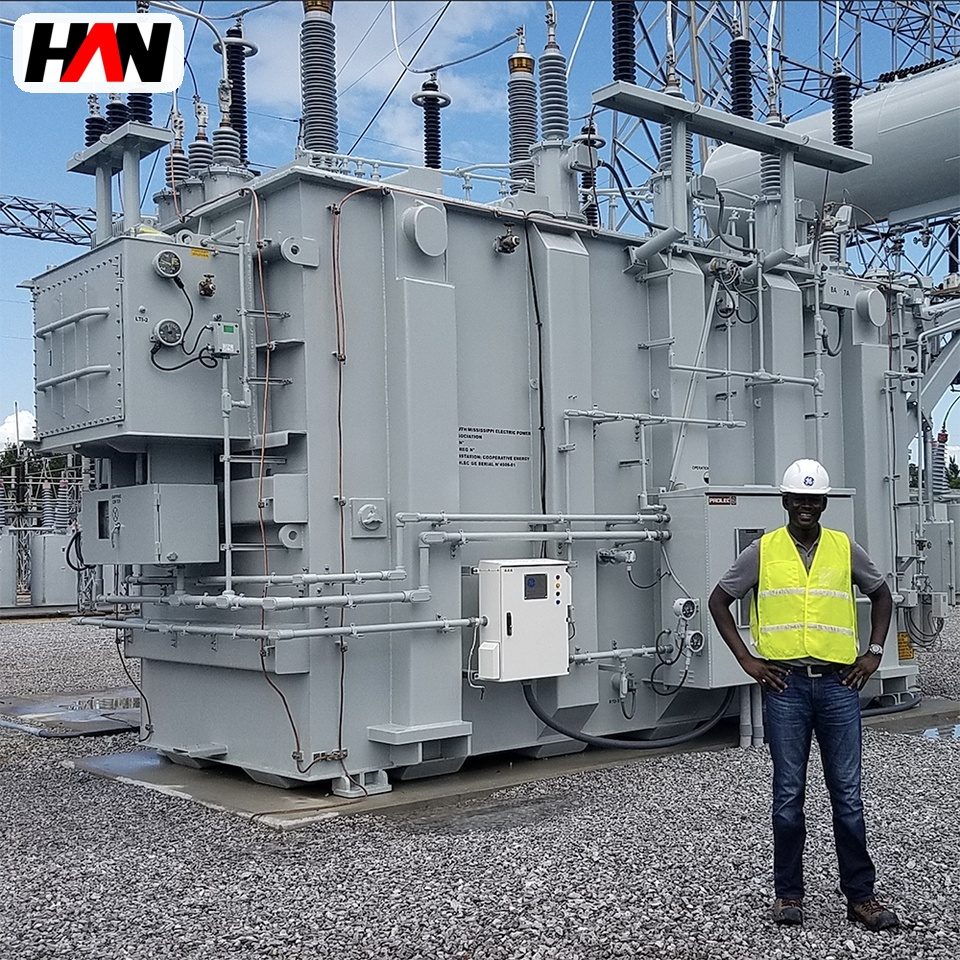
Oil does two jobs in a high-voltage unit: it insulates and it carries heat from the windings to the radiators. Because it expands by roughly one part in a thousand per kelvin, the volume changes by hundreds of litres between a cold night and a loaded afternoon, and that expansion has to go somewhere. A conservator tank above the main tank gives the oil somewhere to go and keeps the main tank full, with a breather drying the air that moves in and out as the level changes.
The instruments that hang off this system are the transformer’s nervous system. A gas-actuated relay in the pipe between tank and conservator collects gas produced by a developing fault and trips on oil surge; it detects slow thermal faults, not just dramatic ones. A pressure relief device on the tank cover opens if internal pressure rises faster than the relay can respond. Dial thermometers read top-oil temperature, and a winding temperature indicator adds a simulated hotspot by passing a current proportional to load through a heater in the bulb. Silica gel in the breather turns from blue to pink as it absorbs moisture, which is a crude but effective humidity indicator.
Oil condition is monitored rather than assumed. Dissolved gas analysis, interpreted against IEC 60599, turns the concentrations of hydrogen, methane, acetylene, ethylene and carbon oxides into an opinion about what is happening inside: arcing, overheating, partial discharge or paper degradation. Acetylene at any significant level is a warning of arcing; ethylene rising with load points to a hot spot. The value of the test comes from the trend, which is why a baseline sample taken at commissioning matters more than any single reading later.
Bushings, clearances and the outside of the tank
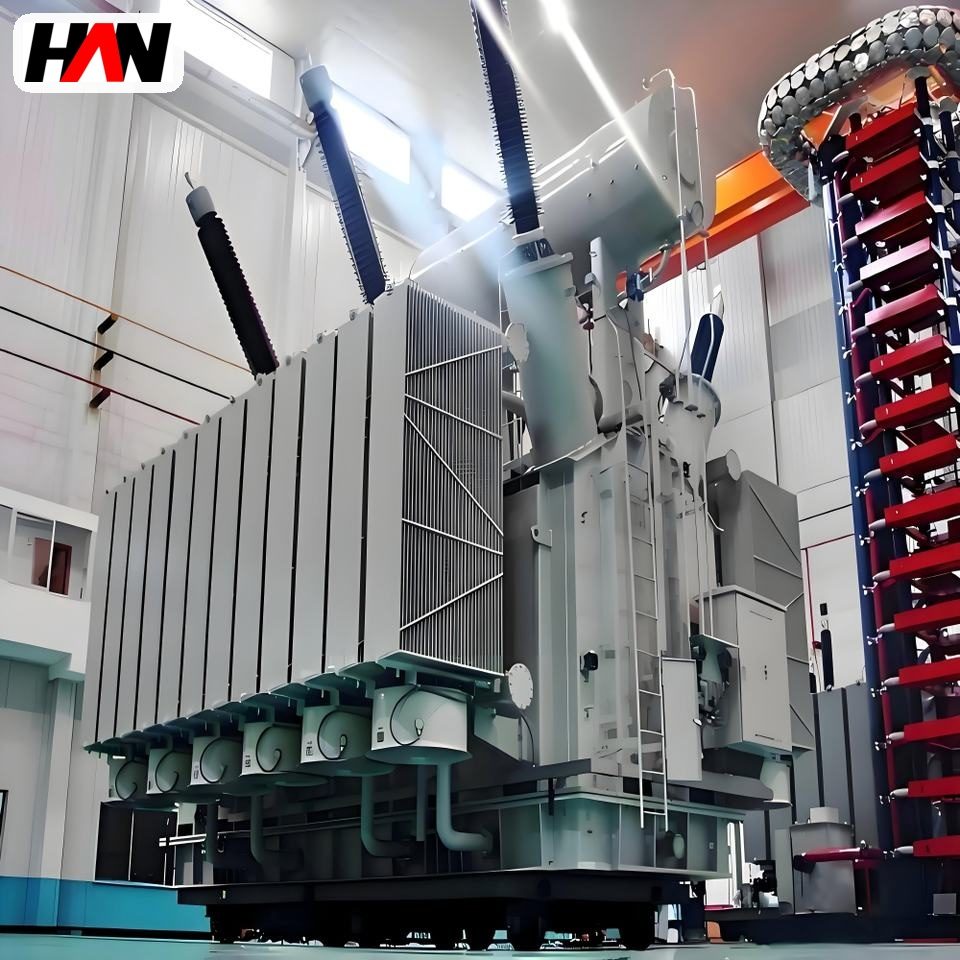
A bushing is a condenser: layers of oil-impregnated or resin-impregnated paper wound around a conductor, with conductive foils between layers to grade the voltage from the conductor to the flange. Grading matters because without it the whole voltage would appear across the last few millimetres of insulation near the flange. Bushings are specified to IEC 60137 with their own insulation level, their own cantilever strength and their own test regime, and a capacitance tap allows tan delta and power factor measurement in service without dismantling anything.
Outside the tank, the design is dominated by air clearance and creepage. Pollution performance is set by the creepage distance relative to the highest voltage, with IEC 60815 giving the framework and site severity classes deciding the multiplier; a coastal or cement-plant site can need a creepage length several times that of a clean inland one. Phase spacing, the height of the terminals above the ground, the clearance to the fence and the safety distances for live-line work all come from the same coordination study, and they are the numbers that decide how much land the substation needs.
Inside the tank: what the windings look like
Most units in this class are core form: a laminated core with three vertical limbs, windings arranged concentrically around each limb, low voltage nearest the core and high voltage outside it. The alternative, shell form, wraps the winding around the limbs in a different topology and is used where a lower height or a particular short-circuit behaviour is needed. Core form dominates because it is easier to manufacture, easier to transport and easier to repair.
The high-voltage winding is usually a disc winding: many flat discs stacked axially, each connected to the next, with oil ducts between them. Disc construction gives a large cooling surface and lets the designer tune the impulse voltage distribution by adjusting interleaving near the ends. The tapping winding is a separate section, placed where its own surge behaviour is manageable, and a stabilizing tertiary in delta is often added so that third-harmonic currents have a path and the zero-sequence impedance is defined.
IEC and IEEE: where the two frameworks meet
| Topic | IEC 60076 | IEEE C57.12.00 |
|---|---|---|
| Voltage reference | Highest voltage for equipment, Um | Nominal system class, kV |
| Insulation level | Lightning and switching impulse from IEC 60071-1 | BIL from the class table, with optional levels |
| Ambient basis | 40 °C maximum, 20 °C annual average | 30 °C average, 40 °C maximum |
| Temperature rise | About 60 K top oil, 65 K average winding | 65 K average winding, 80 K hottest spot |
| Test code | IEC 60076-1, -3, -5 | IEEE C57.12.90 |
| Impedance tolerance | A stated percentage of the declared value | A stated percentage, applied differently |
| Practical outcome | Same physics, different paperwork | Same physics, different paperwork |
The practical consequence is that a unit cannot be “both” without a decision on which document governs. A transformer built to IEC 60076-3 with a 40 °C ambient basis and an IEEE-specified BIL will pass its own tests and may still be judged non-compliant by an inspector working from C57.12.00, because the temperature rise language and the ambient assumptions differ. The right approach is to name the governing standard in the specification, list the exceptions explicitly, and require the test report to state which clause each result satisfies.
Weight, gauge and the site assembly that follows
A 100 MVA, 230 kV unit is not a single transportable object. The complete unit might weigh well over a hundred tonnes with oil; the core and coils alone, without oil, are a different and smaller problem, and the tank may travel as a separate item with its cover off. Road and rail gauges set hard limits on width, height and sometimes length, and those limits feed straight back into the electrical design: a five-limb core, a lower tank profile or a split winding can all be chosen because the tallest possible unit would not fit under a bridge on the only viable route.
Shipping without oil is normal. The core and coils travel in a tank filled with dry air or nitrogen at a slight positive pressure, with a gauge to prove the pressure held for the whole journey and a record of any top-up. That gauge is not a formality: if the pressure fell, moisture entered, and the drying process on site has to be longer and more carefully monitored.
Site work then follows a sequence that cannot be compressed much. The unit is assembled, the oil is processed through a vacuum dehydrator to remove water and gas, the tank is evacuated and filled under vacuum so that the paper absorbs oil without trapping air, and the oil is left to stand while the moisture equilibrates between paper and oil. After that come the field tests: insulation resistance and polarization index, winding resistance, ratio, capacitance and tan delta on bushings and windings, a sweep frequency response baseline for later comparison, and a full dielectric test if the contract calls for one. IEC 60076-3 sets the dielectric levels, and the supervision of oil handling follows the practice in IEC 60422.
Where these units sit in the network
Three placements account for most of the demand. The first is the transmission substation, where a 230 kV or 138 kV line is stepped down to 69 kV or 34.5 kV for a subtransmission network; these units are usually YNd11 with an on-load tap changer on the high-voltage winding and a stabilizing tertiary. The second is generation step-up, where a 13.8 kV generator is matched to a 138 kV or 230 kV bus; here the transformer is often the generator’s only link to the grid and is specified with a higher impedance to limit fault current and a lower sound level because it sits next to a turbine hall. The third is the large industrial or data-campus supply, where a single 69 kV or 115 kV infeed serves a plant that cannot tolerate a long outage.
Upstream of these units sit line breakers, disconnectors, surge arresters and current transformers. Downstream sit medium-voltage switchgear, distribution transformers and, in the industrial case, the process itself. The transformer is the element that cannot be bypassed, which is why the protection scheme around it is usually differential, why a spare unit is sometimes bought with the first one, and why the transport study is worth doing before the purchase order rather than after it.
Specification and commissioning checklist
- Name the governing standard and the exceptions. IEC 60076 with an IEEE BIL is a workable combination only if the temperature rise basis and the ambient reference are written down.
- State the insulation level as a number, not a class. Ask for the impulse and power-frequency levels explicitly, plus the bushing levels, which must be at least as high as the winding.
- Check the transport study before the design freeze. Route gauge, bridge limits, crane capacity at site and the maximum transport mass all constrain the design.
- Require a nitrogen pressure record. A log of the tank pressure from filling to arrival, with the actions taken at any deviation.
- Agree the on-site oil treatment. Vacuum level, oil temperature, processing duration and the acceptance criteria for moisture and breakdown voltage before energisation.
- Take a fingerprint at commissioning. Sweep frequency response, tan delta, excitation current and a dissolved gas sample, so that later measurements have something to be compared with.
- Plan the spares and the access. Bushing spares, gaskets, a spare gas relay and the crane or jacking arrangement for a bushing replacement are cheap at order time and expensive later.
Frequently asked questions
Why is BIL so much higher than the system voltage?
Because a lightning strike on a line produces a wave with a peak far above the nominal voltage, and the transformer has to survive it. The BIL of a 69 kV class unit is 350 kV, about five times the phase-to-phase nominal value. The margin exists to cover the impulse, not normal operation, and it is coordinated with the arresters so that the arrester limits the wave before the winding sees the full test level.
Is a 100 MVA unit always three-phase?
In this voltage range, almost always. Above a certain size and voltage the three-phase unit becomes too heavy or too tall to transport, and three single-phase units are used instead, with a spare phase kept on site. That arrangement costs more but turns a transformer failure into a bushing-and-transport exercise rather than a total loss of the substation.
What does the conservator actually do?
It gives the expanding oil somewhere to go and keeps the main tank completely full, so the windings are never exposed to air. The breather dries the air that moves in and out as the level changes. A sealed tank without a conservator exists, but it needs a gas cushion and different pressure management, and it is less common at these voltages.
Can the unit be tested at site instead of at the factory?
Some tests can, some cannot. Impulse testing needs a laboratory impulse generator and is done at the factory. Insulation resistance, ratio, winding resistance, tan delta and frequency response are practical on site and form the commissioning record. The contract should state which tests are witnessed at the factory, because that is the only point at which a design problem can be found before the unit is on a truck.
How is impedance chosen at this size?
By the fault level the downstream network can tolerate and by the voltage regulation the load can accept. Typical values sit between 10 % and 14 % on the unit’s own base. Higher impedance reduces fault current and the mechanical duty on everything downstream, and increases reactive loss and voltage drop. The choice is a system study, and both the utility and the plant protection settings depend on the outcome.
Insulation level, impedance, cooling stages, tap range and transport configuration are agreed per project, so a unit in this class is engineered against a network study and a route survey rather than selected from a catalogue. Send the system voltage, the fault level and the transport route and the specification can be closed from those three inputs.