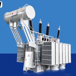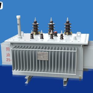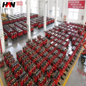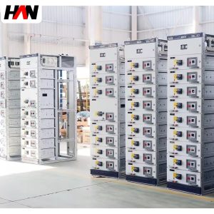
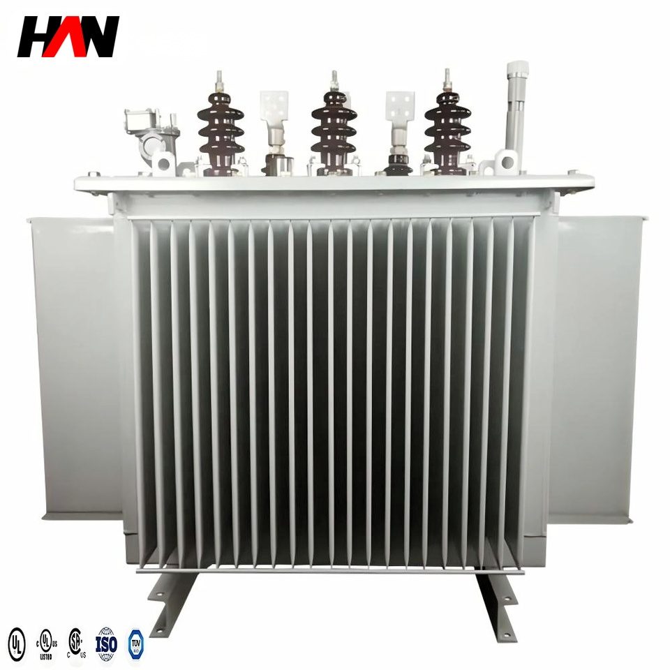
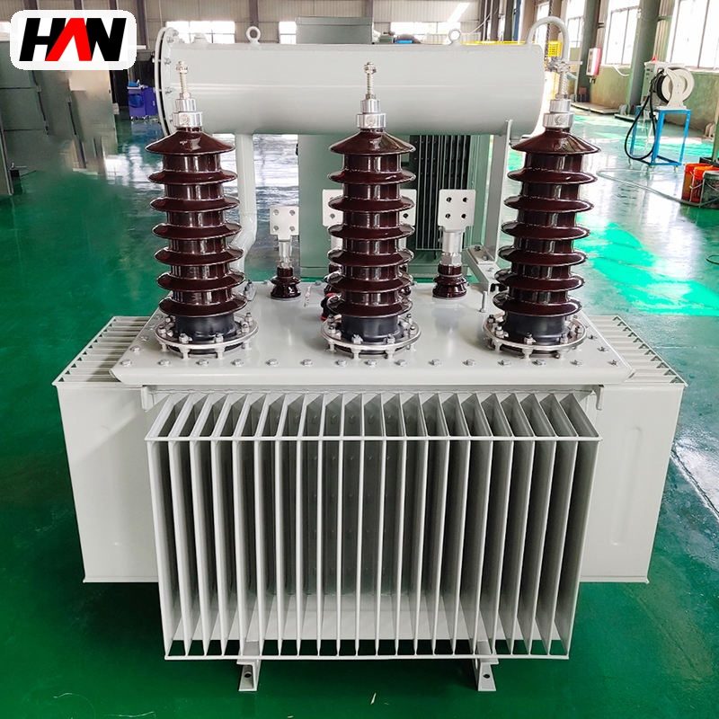
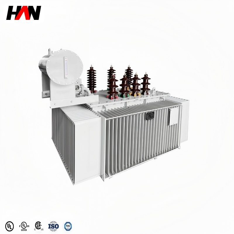
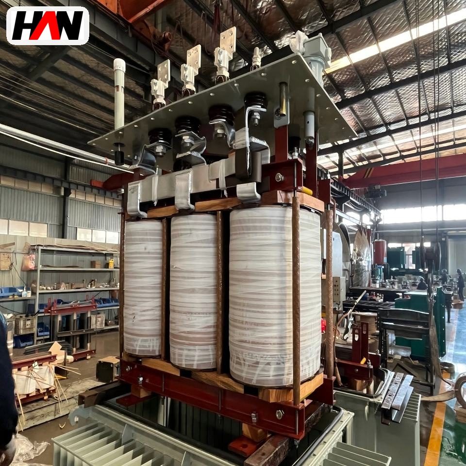
An S11 transformer is the quiet majority of medium-voltage distribution. It stands between a 10 kV or 35 kV feeder and the 400 V board of a factory, a hospital, a housing block or a pumping station, and it does that job for twenty-five years with almost no attention. Three-phase, oil-immersed, naturally cooled, wound on a laminated core and sealed into a steel tank. Nothing about the description sounds advanced, and that is the point: the design has been optimised so far that what separates one supplier from another is detail rather than concept. The detail is worth understanding, because the choices inside a single unit decide how much energy it burns while idle, how hot its windings run on a summer afternoon, and whether its tank will still be dry inside after a decade of monsoon air. This page walks through the naming, the construction, the rating table, the two kinds of loss, the temperature limits behind the six-degree rule, and the vector groups that decide how an earth fault behaves on the low-voltage side.
At a glance
| Rated power | 25 – 2 500 kVA |
| High-voltage winding | 6 / 10 / 11 / 20 / 35 kV |
| Low-voltage winding | 0.4 / 0.415 / 0.69 kV |
| Cooling | ONAN, oil natural air natural |
| Vector group | Dyn11 standard, Yyn0 or Yd11 on request |
| Short-circuit impedance | 4 % to 4.5 % |
| Off-circuit tap range | ± 2 × 2.5 % |
| Winding temperature rise | 65 K average, 60 K top oil |
| Design standard | IEC 60076-1, IEC 60076-2, IEC 60076-3 |
What the designation actually means
S11 comes out of the naming habit used across a large part of the Asian market, and it reads in two halves. The letter marks a three-phase oil-immersed unit; a single-phase equivalent would carry a different letter, and a dry-type unit another. The number is a performance generation, not a power rating and not a voltage class. Successive generations have carried higher numbers as core steel, lamination grade and winding geometry improved, and each step bought lower no-load loss for the same rating. A buyer who reads the two digits as kilovolt-amperes will misread every quotation that crosses the desk.
In the international framework the equipment belongs to IEC 60076, the standard series for power transformers. Part 1 covers general requirements and the definitions everything else depends on, part 2 covers temperature rise, part 3 covers insulation levels and dielectric testing, part 5 gives the rating values for short-circuit impedance, and part 11 handles the dry-type branch of the family. A distribution transformer is simply the small end of that range: units that sit close to the load, feed a low-voltage board directly, and are ordered by the hundred rather than designed one at a time.
The boundary between a distribution transformer and a power transformer is a convention rather than a physical law. Roughly speaking, units up to a few megavolt-amperes that step down to utilisation voltage are distribution units; anything designed for transmission, generator step-up or interconnection is a power transformer. The S11 range described here spans 25 kVA to 2 500 kVA, which keeps it firmly inside distribution duty.
Construction and the path the current takes
The magnetic circuit is a laminated core of grain-oriented silicon steel, stacked and clamped so the flux has a closed path with as little air gap as possible. The high-voltage winding sits outside the low-voltage winding on each limb, a concentric arrangement that puts the larger insulation gap where the voltage stress is highest and keeps the low-voltage winding close to the core, where its shorter mean turn saves copper. Windings are copper, sometimes aluminium in the smallest ratings, wound in layers or in discs depending on the voltage class.
The assembled core and windings are dried, vacuum-impregnated and lowered into a steel tank filled with mineral insulating oil. The oil does two jobs at once: it carries heat from the winding surface to the tank wall by convection, and it fills the space inside the insulation where air would break down far sooner. Tank walls in smaller ratings are pressed into corrugations that add surface area and act as expansion elements, which is why a sealed corrugated tank can absorb the oil’s thermal expansion without any external tank.
High-voltage connection is made through porcelain or composite bushings on the cover; the low-voltage side leaves through flat-bar bushings or a cable box. A tap changer sits on the high-voltage side, usually an off-circuit link plate under a cover that must be opened with the unit isolated. Lifting lugs, jacking pads, an earthing terminal, a rating plate and, on larger units, a dial thermometer and a pressure relief device complete the list.
Ratings, and what each number controls
A rating plate carries perhaps twenty numbers, and a project usually turns on six of them. The table collects the ones that change a design.
| Parameter | Typical value | What it constrains |
|---|---|---|
| Rated power, Sr | 25 – 2 500 kVA | Continuous apparent power at the secondary terminals |
| Highest voltage for equipment, Um | 7.2 – 40.5 kV | Clearances, bushing length and the dielectric test level |
| Rated voltage ratio | 10 000 / 400 V and similar | Turns ratio, and the tap range that corrects for feeder voltage |
| Rated frequency | 50 Hz or 60 Hz | Core flux density, hence core area and no-load loss |
| Short-circuit impedance, uk | 4 % up to 630 kVA, 4.5 % above | Secondary fault current and voltage dip on motor starting |
| No-load loss, P0 | Set by loss grade, not by kVA alone | Standing energy cost for every hour the unit is energised |
| Load loss, Pk | Referenced to 75 °C | Copper section, winding height and the cooling surface needed |
| Vector group | Dyn11, Yyn0, Yd11 | Phase displacement and the path for zero-sequence current |
| Temperature rise | 65 K winding, 60 K top oil | Insulation life, and how much overload a hot day allows |
| Insulation level | e.g. 170 kV lightning impulse at 36 kV class | Withstand against switching and lightning surges, per IEC 60076-3 |
| Off-circuit taps | ± 2 × 2.5 % | Compensation for a feeder that sits high or low all year |
| Installation altitude | 1 000 m without correction | Air density, hence external insulation and cooling |
Two of those rows are frequently misread. The first is power. Kilovolt-amperes measure apparent power, the product of voltage and current, and they do not shrink when the load has a poor power factor. A 1 000 kVA unit feeding motors at 0.85 power factor delivers 850 kW of real power and the remaining 150 kVA of magnetising and leakage burden regardless. The second is voltage. A ratio written as 10 000 / 400 V refers to line-to-line values on both sides. Where a nameplate shows 480Y/277 V, the 277 V is the line-to-neutral value, obtained by dividing 480 by the square root of three, and the Y marks a star point brought out for earthing.
Engineering note. Catalogue lines that run “6 kV 10 kV 20 kV 35 kV 50 kVA 100 kVA 200 kVA 1 000 kVA 2 500 kVA” in a single string are describing the outer envelope of a product family, not a buildable unit. A 2 500 kVA transformer at 35 kV and a 25 kVA transformer at 6 kV share a manufacturing line and nothing else: winding type, tank size, impedance, tap arrangement and shipping mass all differ. When a project needs a real unit, fix four numbers first — rated power, both winding voltages, vector group, impedance — and the rest of the specification writes itself around them.
Where the losses come from, and why a low-loss unit costs more
Loss in a transformer splits into two parts that behave in opposite ways. No-load loss, also called iron loss or core loss, appears the moment the high-voltage winding is energised and stays roughly constant whatever the load does. It comes from two mechanisms inside the laminated core: hysteresis, the energy needed to swing the magnetic domains back and forth on every cycle, and eddy currents, small circulating currents induced in the steel itself. Thin laminations coated with insulating varnish interrupt the eddy path; better grades of grain-oriented steel reduce hysteresis and allow a higher flux density before saturation. Load loss, also called copper loss, appears only when current flows, and it rises with the square of the load, because it is resistive heating in the windings plus stray loss in the tank walls and structural steel.
That difference in behaviour is the whole logic of loss grading. A factory running two shifts might load a unit to 60 percent for sixteen hours and 25 percent overnight; because copper loss falls with the square of current, the energy bill at night is dominated by iron loss. A design with a larger core, a better steel grade and more copper in the windings cuts both figures, and the manufacturer sells it as an upgrade rather than as standard. The hardware costs more: more core steel, more copper, a taller tank, more oil. The operating cost falls every hour for the whole life of the unit.
Whether the upgrade pays depends on three project variables, and none of them is in the catalogue. The first is loading pattern: a transformer that runs near rated load most of the day saves more from reduced load loss, while one that is energised but lightly loaded saves more from reduced no-load loss. The second is the price of energy over the life of the asset, including whatever escalation the owner expects. The third is the discount rate used to compare money spent now with money saved later. A capacity evaluation that ignores all three and compares only purchase price is comparing the smaller half of the cost.
| Option | What changes | Best fit |
|---|---|---|
| Baseline oil-immersed grade | Standard core steel, standard copper section | Short duty cycles, temporary supply, sparsely loaded feeders |
| Reduced-loss grade | Higher steel grade, stepped core, larger conductor area | Continuously energised units, high energy price, long asset life |
| Dry-type, cast resin | No oil, higher fire safety, lower overload margin | Indoor rooms, basements, tunnels, areas with strict fire rules |
| Larger unit at low load | Lower copper loss per kW delivered, higher standing iron loss | Loads expected to grow, where spare capacity has a use later |
Heat, temperature rise and the six-degree rule
Every loss inside a transformer becomes heat, so a 1 000 kVA unit losing two percent of its throughput is dissipating tens of kilowatts inside a steel box. Under ONAN cooling the oil rises past the windings, flows to the tank wall, gives up heat to the air by convection and radiation, and returns down the cooler wall. Corrugated walls and radiators exist for no other reason than to add surface area to that loop. Temperature rise is measured above ambient, not in absolute degrees, because the same unit behaves differently in a 20 °C workshop and a 45 °C roof enclosure.
IEC 60076-2 sets the limits for oil-immersed units cooled by natural circulation: 60 K rise for the top of the oil, 65 K for the average winding, with a hot-spot allowance on top. Those numbers only hold inside the ambient conditions the standard assumes, and a site that regularly exceeds 40 °C needs a derated rating or a forced-cooling variant rather than a promise. The reason the limits are tight is insulation. Cellulose paper immersed in oil degrades by a chemical process that accelerates sharply with temperature, and the rate roughly doubles for every additional 6 K at the hot spot. That figure is an empirical rule of thumb rather than a clause in any standard, quoted across the industry to explain why a modest overload tolerated for a few hours is not the same as a permanent one.
Practical consequences follow. A unit loaded to 120 percent on a hot afternoon ages faster during those hours than the annual average suggests. A unit that never reaches its rated load because the plant expanded more slowly than forecast will outlive its design life comfortably. Oil tests track the same process from the outside: acidity, moisture and dissolved gas all move before the paper fails, which is why periodic sampling matters more than the inspection of the paint.
Vector groups, zero sequence and why Dyn11
The vector group is written as a pair of letters and a number. Capital letters describe the high-voltage winding, lower case the low-voltage winding; D or d means delta, Y or y means star, n means a neutral brought out, and the number is the phase displacement of the low-voltage phasors against the high-voltage ones in clock hours. Dyn11 therefore means a delta high-voltage winding and a star low-voltage winding with a neutral, the low-voltage side lagging by 30 degrees.
The choice matters because it decides what happens to zero-sequence current. A delta high-voltage winding gives circulating zero-sequence current a path that never reaches the supply, so the transformer acts as a barrier to triplen harmonics and to zero-sequence unbalance from the low-voltage side. On the low-voltage side, a star point with a neutral allows single-phase loads to be connected phase to neutral and gives earth fault current somewhere to flow, which is what allows overcurrent protection to see an earth fault at all. A Yyn0 unit with an ungrounded or weakly grounded neutral behaves quite differently under unbalanced load: the neutral shifts, phase voltages wander, and equipment on the healthy phases sees overvoltage.
Dyn11 has become the default in most distribution practice for exactly this combination: low-voltage earth faults produce a healthy current for the protection to detect, triplen harmonics stay out of the high-voltage network, and the 30-degree displacement is easy to parallel with another Dyn11 unit. Paralleling two transformers with different vector groups is not a matter of matching ratios. The 30-degree displacement produces a voltage difference between the secondaries that drives a circulating current limited only by the two impedances.
Sealed tank against conservator
Oil expands when it warms, and something has to absorb that volume. Two constructions answer the problem in different ways, and the choice affects maintenance more than it affects performance.
| Criterion | Sealed corrugated tank | Tank with conservator |
|---|---|---|
| Expansion volume | Corrugations flex with oil temperature | Oil moves into an expansion tank above the cover |
| Contact with outside air | None, the tank is welded shut | Breather admits air as the oil level moves |
| Routine attention | Oil sampling only | Silica gel renewal, breather check, oil level sight glass |
| Moisture ingress risk | Low | Depends on the breather being serviced |
| Oil volume in service | Smaller, sealed for life | Larger, with a reserve the operator can see and top up |
| Typical position | Pole, platform, kiosk, urban distribution | Larger ratings, unattended substations where oil level is monitored |
Engineering note. A sealed tank is not a maintenance-free licence. Water still enters through gaskets, bushing seals and cable boxes, and it collects at the bottom of the tank where the winding insulation sits. Sampling a sealed unit every few years costs little and catches moisture before it drives an insulation failure. Where a site floods, mount the unit on a plinth above the recorded flood level rather than relying on the tank’s ingress rating.
Where it sits in a distribution chain
The usual chain runs from a ring main unit or a load-break switch on the medium-voltage feeder, through the transformer, into a low-voltage main breaker and onward to a distribution board. Upstream of the transformer sit the switchgear, the protection relays and the metering; downstream sit the busbars, the feeders and the final circuits. Two ratings tie the ends together. The transformer’s impedance sets the fault level the low-voltage board must withstand, and the transformer’s continuous rating sets the current the board must carry. A 1 000 kVA unit at 4.5 percent impedance delivers a secondary fault current several times its rated current, and the board has to be bought for that number.
Sectors that buy these units in volume are the ones with a moderate medium-voltage load spread over a site: water and wastewater works, cement and aggregate plants, textile and food factories, cold stores, hospitals, schools, commercial towers and residential compounds. Solar and wind projects use the same construction as a step-up or collector unit where the plant is small. In each case the operating pattern differs, and so does the case for a low-loss grade: a works running three shifts values every hour of iron loss, while a standby supply energised a few weeks a year does not.
Selection and commissioning checklist
- Fix the load, not the spare. Size on measured or calculated demand plus a deliberate margin, and write the margin down. Oversizing to be safe raises standing loss for the next twenty years.
- Confirm the actual system voltage. A feeder nominal at 10 kV may sit at 10.5 kV at the point of connection. Choose the tap range from the measured voltage, not from the drawing title block.
- State the vector group explicitly. If the existing network is Yyn0 and the new unit is Dyn11, the two cannot be paralleled, and protection settings written for one may not grade with the other.
- Check impedance against the low-voltage board. A lower impedance gives better voltage regulation but a higher fault level. Ask for the calculated secondary fault current before the board is ordered.
- Decide the loss grade on an energy calculation. Ask for no-load and load loss figures at the offered rating, then run the life cost with the real tariff and the real load profile.
- Plan access and ventilation before delivery. A 2 500 kVA unit needs a crane, a hardstanding and clear air on all four tank walls. A unit boxed into a niche with one open side will run hotter than its rating assumes.
- Agree the tests. Ratio and polarity, winding resistance, insulation resistance, applied and induced voltage withstand, impedance and load loss, no-load loss, and an oil dielectric test before energisation.
Frequently asked questions
Does the number in S11 tell me the power rating?
No. The digits mark a design generation, and higher generations generally mean lower no-load loss for the same rating. The power rating appears separately on the plate, in kilovolt-amperes, and ranges from 25 kVA to 2 500 kVA for this construction.
Can a 50 Hz unit run on a 60 Hz network?
It can run at 60 Hz at the same voltage, because the higher frequency reduces flux density in the core; the unit simply becomes slightly under-fluxed and the no-load loss changes. The reverse is the dangerous direction: a 60 Hz design energised at 50 Hz sees higher flux density, draws more magnetising current and may saturate.
What is the difference between 400 V and 415 V on the low-voltage side?
Both are standard utilisation voltages in different regions, and the difference is absorbed by the tap changer or by the design ratio. What matters is that the ratio matches the actual feeder voltage, so that the secondary sits near nominal at the load, not at the transformer terminals.
Why is the impedance only 4 to 4.5 percent?
Distribution transformers are kept at low impedance so voltage regulation stays tight and motor starting dips stay tolerable. The trade is a higher secondary fault current. Larger units and parallel operation usually step up to higher values to keep the low-voltage board’s fault rating within reason.
Is oil-immersed equipment allowed inside a building?
It is, subject to local fire rules, and usually only in a dedicated room with a fire-rated boundary, an oil containment pit and ventilation to outside. Where those rules are strict, a dry-type unit is the simpler route, at the cost of a lower overload margin and a higher purchase price.
Ratings, taps, impedance, vector group, tank finish and loss grade are all fixed per order, so a unit can be matched to a specific feeder rather than to a catalogue page. Send the load schedule and the measured medium-voltage level and the electrical specification can be settled from those two documents.