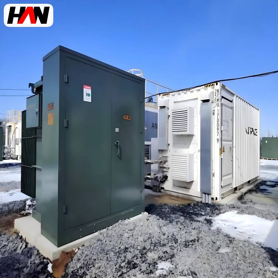
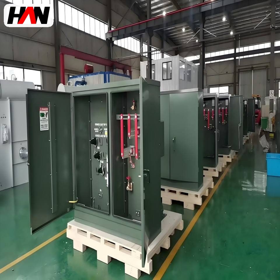
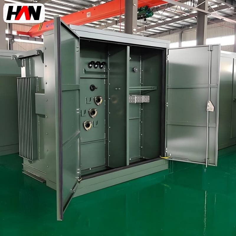
Loop feed is the arrangement a network designer reaches for when a single outage is expensive. Instead of one cable arriving at the transformer and stopping there, two cables arrive — one from each side of the loop — and a switch inside the enclosure decides what connects to what. In the normal state the unit passes power straight through from one cable to the other while its own transformer runs off the same bus. Open one switch and the transformer is isolated while the loop keeps feeding everything beyond it. Lose one cable and the far side is back-fed from the other direction, so the customers downstream never notice. This page deals with the larger end of that format: 1 000 to 3 000 kVA units stepping 12.47 kV or 13.8 kV down to 480Y/277 V, the kind that stand behind a data hall, a factory or a business park. It covers the switching logic, the compartment and bushing arrangement, the thermal and acoustic limits a big transformer inside a small box runs into, and the reliability argument that justifies the extra cost.
At a glance
| Rated power | 1 000 – 3 000 kVA |
| High-voltage winding | 12.47 or 13.8 kV, delta |
| Low-voltage winding | 480Y/277 V, four wire |
| Frequency | 60 Hz |
| Feed arrangement | Loop feed, four high-voltage bushings |
| Switching | Four-position sectionalising, load-break |
| Impedance | Around 5.75 % at these ratings |
| Impulse level | 95 kV, 15 kV class system |
| Standards | IEEE C57.12.34, C57.12.00, C57.12.90 |
What loop feed actually changes
A radial pad-mounted unit has two high-voltage bushings, or three counting the neutral point, and one cable coming in. It is the end of a branch. A loop-feed unit has two sets of bushings, one labelled for the incoming side and one for the outgoing side, and the two are connected through a switch. The cable that leaves does not stop at the next customer; it continues to the next pad, and eventually the loop closes back at the source. The supply can travel in either direction around that ring.
The switch is the heart of the arrangement. In the common four-position version, each phase can be set so that the transformer is fed from the A side, from the B side, from both with the loop closed through, or from neither with the transformer isolated and the loop still made. Because closing onto a live cable is a routine operation, the switch has to be load-break rated: it interrupts the magnetising current of the transformer and the loop current of the feeder without drawing an arc across the compartment.
Two consequences follow. The first is that the high-voltage bushings are dead-front. A loop-feed cable is worked on while the far end may still be energised from the other direction, so the operator has to be able to test and isolate at the bushing rather than at a remote switching point. An exposed live-front termination would make that procedure impossible. The second is that the loop-through bushings carry the full feeder current, not just the transformer current — a 2 000 kVA unit draws under a hundred amps at 13.8 kV, but the loop cable may carry several hundred — so the bushings, elbows and switch bus on the through path are rated for the feeder rather than for the transformer.
Switching logic, normal and abnormal
The value of the arrangement shows up in the operating states rather than in the component list. The table describes the four that matter.
| Condition | Switch position | Effect on supply |
|---|---|---|
| Normal operation | Loop closed, transformer on both sides | Power flows through the ring; the unit carries its own load |
| Transformer maintenance | Transformer isolated, loop through | Only this unit’s low-voltage load is lost; the ring keeps feeding others |
| Cable fault on the A side | A side open, B side closed | Unit back-fed from B; the faulted section is isolated for repair |
| Fault inside the transformer | Both sides open after fuse operation | Fuse clears, loop is restored by closing the through path manually |
Fault isolation is where the design earns its cost. A fault in the transformer is cleared by the insert-type current-limiting fuses in the high-voltage compartment, which operate fast enough to limit the energy let through before the first current peak. A fault in the cable is located by sectionalisers and switches along the ring, and once the faulty section is opened, the healthy part of the ring is re-energised from the other end. On a radial system the same fault leaves everyone beyond it dark until the cable is repaired, because there is no second path to back-feed.
The operator’s task is worth stating plainly, because the switching sequence is what the equipment is designed around. Isolate the transformer, confirm dead at the test point in the elbow, open the loop, work, then close in the reverse order. Every load-break operation happens inside an enclosure with the door open and a person standing next to it, which is why the arc containment, the interlocking and the dead-front geometry are specified rather than assumed.
Ratings, and what each figure governs
| Parameter | Typical value | What it governs |
|---|---|---|
| Rated power | 1 000 – 3 000 kVA | Secondary current at 480 V, and the low-voltage board rating |
| Primary voltage | 12 470 or 13 800 V, delta | Turns ratio and the insulation class of the high-voltage side |
| Secondary voltage | 480Y/277 V | Phase-to-phase and phase-to-neutral levels at the service |
| Impedance | Around 5.75 % | Fault current the low-voltage equipment must withstand |
| Bushing rating | 200 A transformer, 600 A loop through | Whether the feeder can be looped at full load |
| Switch rating | Load-break, four position | Whether the loop can be switched under load or only off-load |
| Fuse class and rating | Current-limiting, matched to full-load current | Transformer protection and coordination with upstream devices |
| Taps | Two 2.5 % above and below | Secondary voltage against the actual feeder level |
| Temperature rise | 65 K average, 80 K hot spot | Insulation life and the cooling the enclosure must provide |
| Sound level | Declared at a stated distance | Setback from a property line or a neighbouring use |
| Enclosure protection | IP54 on the low-voltage compartment | Dust and water ingress into terminations and metering |
The numbers that trip people up are the voltage ones. 480Y/277 V means a four-wire star secondary with 480 V between phases and 277 V from any phase to the neutral, which is 480 divided by the square root of three. That 277 V is what feeds lighting circuits and single-phase loads, and the ratio between the two is fixed by the winding, not by a setting. Likewise 12 470 V and 13 800 V are both line-to-line values on a 15 kV class system; the difference is a utility’s choice of feeder standard, and the transformer’s insulation class is the same either way.
Engineering note. The primary is normally delta connected, and that choice is not arbitrary. A delta primary blocks zero-sequence current from reaching the loop, so an unbalanced secondary load or a third-harmonic component cannot circulate out into the feeder and disturb other customers. The star point on the secondary gives the earth fault current a defined path back through the neutral, which is what makes downstream ground fault protection work at all. Where a project asks for a different connection to match an existing installation, the change affects protection settings as much as it affects the transformer.
Heat and noise when a large unit sits in a small box
Losses in a 3 000 kVA transformer add up to tens of kilowatts, and all of that energy leaves as heat through the tank surface. No-load loss, produced by hysteresis and eddy currents in the laminated core, is present whenever the unit is energised. Load loss, produced by resistance in the windings plus stray loss in the tank and structural steel, rises with the square of the load current. In open air a tank rejects that heat by convection and radiation without help. Inside an enclosure the available air is warmer, the airflow is restricted by louvres, and the sun adds load to the cover, so the same tank runs hotter than its open-air rating assumes.
Enclosure design works on the air path rather than on the tank. Inlet louvres sit low on one face, outlet louvres sit high on the opposite face, and internal baffles force the air to travel across the radiators instead of short-circuiting straight up the wall. Radiators are set back from the louvres far enough for a chimney effect to develop, and the compartment is sized so that the air leaving the top is not immediately drawn back in. Where the units are bigger than the box can cool naturally, the option is a forced-air cooling stage — fans that raise the rating for a defined period — but that trades thermal capacity for a fan that must be maintained and a noise source that must be accounted for.
Heat is also a life question, not only an efficiency one. Insulation ageing tracks the hot spot, and the industry rule of thumb says the chemical rate roughly doubles for every 6 K of extra hot-spot temperature — an empirical rule, not a standard clause, but a useful way to see why a unit run at its limit every afternoon for years will not reach the life a lightly loaded unit reaches. A 3 000 kVA unit at 90 percent load in a hot climate is therefore a different asset from the same unit at 60 percent.
Sound has the same origin. Core magnetostriction makes the core expand and contract slightly twice per cycle, which at 60 Hz puts the fundamental tone at 120 Hz, with harmonics above it. Tank walls radiate that vibration, and an enclosure either attenuates it or amplifies it depending on how the panels are stiffened and where the unit sits relative to them. For a data centre or a business park the limit is usually set at the property line rather than at the transformer, so the design question becomes distance, barrier and core flux density rather than a single decibel figure.
Loads of the kind these units serve make the thermal problem harder. Rectifiers, uninterruptible supplies and variable-speed drives draw non-sinusoidal current, and the harmonic components increase eddy and stray loss in the windings and the tank beyond what a sinusoidal load of the same rms value would produce. A unit sized on kVA alone, applied to a heavily non-linear load, runs hotter than its nameplate suggests. The practical answers are a lower design flux density, a larger conductor section, or simply the next rating up.
Comparing feed arrangements
| Criterion | Radial pad | Loop feed pad | Spot network |
|---|---|---|---|
| Cable cost | Lowest, one run | Higher, ring needs a return path | Highest, several primaries per site |
| Outage on one cable | Load lost until repair | Restored from the other side | Restored automatically by network protectors |
| Maintenance access | Unit off, load off | Unit off, loop stays live | Unit off, load carried by the others |
| Fault level at 480 V | One unit’s contribution | One unit’s contribution | Sum of all units, so breakers are bigger |
| Footprint per kVA | Smallest | Slightly larger, two bushing sets | Largest, needs a vault or a room |
Where the arrangement earns its place
The economics of loop feed are settled by the cost of an outage rather than by the cost of the equipment. A data hall running critical loads cannot accept an unplanned interruption to change a fuse; the ring gives a maintenance path that keeps the load alive. An industrial park with continuous process plant values the same property, and so does a hospital campus or a light-rail traction supply point. A housing estate or a warehouse development usually cannot justify the extra cable, and a radial unit is the correct answer there.
Data centres add their own constraints. The 480Y/277 V secondary feeds uninterruptible supplies and power distribution units directly, so the transformer’s impedance affects the fault level the downstream switchgear has to interrupt and the voltage dip every time a large load steps. Two units are often run in parallel for redundancy, which requires matched impedance and matched ratio, and the paralleling point has to be designed so one can be isolated without dropping the load. The enclosure then has to reject heat from both the transformer and the switchgear inside it, and do so quietly enough for a site with a noise condition attached to its planning consent.
Industrial parks place the same unit at the edge of a plot, feeding a plant’s main board. The loop there often runs along the internal road, serving several tenants, so a fault on one tenant’s cable does not take out the neighbours. The switching sequence is written into the site’s operating procedure, and the unit is specified with the bushings, fuses and switch that procedure assumes.
Selection and commissioning checklist
- Confirm the loop current. The through path carries the feeder, not the transformer. Bushings, elbows and switch bus must be rated for the larger of the two.
- Decide the switch type from the operating procedure. Load-break four-position switching is the usual choice; off-load switching is cheaper but limits how the ring can be operated.
- Check impedance against the low-voltage board. At 3 000 kVA the secondary fault current is large enough to drive the choice of breaker, not the other way round.
- Match parallel units exactly. Impedance, ratio, tap position and connection must correspond, or the units will circulate current between themselves instead of sharing load.
- Size the enclosure for the real ambient. A unit under a sunshade at 45 °C ambient needs a different rating from the same unit in shade at 30 °C.
- State the sound requirement at the boundary. Distance and barrier are cheaper than a low-noise design, but only if the site plan allows them.
- Agree the tests and the documentation. Ratio, resistance, polarity, impedance, no-load and load loss per the test code, plus a functional check of every switch position and a fuse coordination study.
Frequently asked questions
Can a loop-feed unit be converted from a radial one?
Not in the field. The change needs a second set of bushings, a different switch, additional bus and a redesigned compartment. It is a factory build decision, taken when the network is designed rather than when a spare unit is needed.
Is the loop switch operated live?
The loop is switched under load as a normal operation, which is why the switch is load-break rated and why the bushings are dead-front. Closing or opening the loop with the transformer energised is routine; touching a termination is not, and the test point in the elbow exists so that a dead check can be made safely.
Why 480Y/277 V instead of 400 V?
It is the North American commercial and industrial standard for this kind of distribution, and it suits the equipment built for that market — motors, drives, lighting and uninterruptible supplies. A project in a 400 V market uses a different secondary winding for the same primary.
What happens if one fuse blows?
The transformer is single-phased and the remaining phases carry unbalanced current, which is why the condition is treated as an alarm rather than left in service. The fuse is replaced from outside with a stick, and the load is normally transferred or restored once the cause is found.
Do two 1 500 kVA units beat one 3 000 kVA unit?
For availability, usually yes: one unit can be maintained while the other carries a reduced load, and a failure removes half the capacity rather than all of it. For capital cost, space and simplicity, the single unit wins. The choice is a reliability calculation, not an electrical one.
Bushing count, switch type, fuse class, impedance, tap range and compartment layout are all fixed per order, so the unit can be matched to a specific ring rather than to a standard drawing. Send the network single-line diagram and the secondary fault level and the configuration can be settled from those two documents.