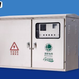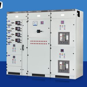
A PZ30 board is the last electrical enclosure in the chain: the small, wall-mounted box that sits inside an apartment, a shop unit or a service corridor and feeds the final circuits. It holds a row or three of miniature circuit breakers on a DIN rail, a residual current device, and the neutral and earth bars, behind a door that anyone can open. Ratings are modest by industrial standards — 63 A to 125 A incoming, 12 to 45 ways, 230 V single-phase circuits mixed with 400 V three-phase ones — yet this is the equipment that ordinary people touch, reset and occasionally get hurt by. This page explains how the board is arranged, why its thermal limits are tighter than the numbers suggest, how selection and residual current protection are meant to work together, and where the boundary sits between a final board and an industrial distribution cabinet.
At a glance
| Rated operational voltage | 230 / 400 V AC |
| Incoming current | 63 – 125 A |
| Ways | 12 – 45 single-pole ways |
| Rows | 1 – 3 DIN rails |
| Outgoing devices | MCB and RCBO, 6 – 63 A |
| Residual current protection | 30 mA, types AC / A |
| Degree of protection | IP30 – IP41 |
| Design standard | IEC 61439-1 and 61439-3 |
| Mounting | Surface or recessed, wall |
What a final board is
PZ30 is a regional type reference for a terminal combination board: a small enclosure, usually of insulated moulding or light sheet steel, arranged as one to three DIN rails with a busbar comb behind the devices. Its international equivalent in function is the consumer unit, and the relevant standard is IEC 61439-3, which covers distribution boards intended to be operated by ordinary persons. That phrase is the heart of the matter. Everything about the design assumes the door will be opened by someone with no electrical training and no test equipment.
Part 3 sits inside the IEC 61439 family, so the general rules of Part 1 still apply: design verification, routine verification, temperature-rise limits, clearances, protective bonding and a declared short-circuit withstand. What Part 3 adds is a set of constraints suited to small boards handled by lay people — a bounded voltage and incoming current, construction that keeps live parts out of accidental reach, and identification that a non-technical person can follow. The board is not a lesser product; it is a product with a different user in mind.
How the box is arranged
The layout follows the current. Supply enters at the main switch, passes through the residual current device, then reaches a comb busbar that feeds the miniature breakers in a row. Neutral and earth are kept on separate bars and are never linked downstream of the supply point; the separation of those two conductors is what allows the residual current device to detect a fault at all, because it works by comparing the current going out on the phase with the current returning on the neutral.
Mixing single-phase and three-phase circuits in one board is normal, and it is where layout discipline matters. A three-pole breaker needs three adjacent positions and its phases must be taken from three different comb teeth, so the row has to be planned rather than filled from left to right. Spread the single-phase circuits across the phases as evenly as the load allows: an unbalanced board heats one comb tooth more than its neighbours and gives a misleading impression of spare capacity.
Ratings and what they mean in a small enclosure
| Parameter | Typical value | What it limits |
|---|---|---|
| Rated operational voltage, Ue | 230 / 400 V | Whether three-phase ways may be included |
| Rated insulation voltage, Ui | 400 / 500 V | Clearances on the comb and between ways |
| Rated current of the incomer | 63 / 100 / 125 A | Total connected load and comb rating |
| Number of ways | 12 – 45 | Spare capacity and heat density |
| Outgoing device rating | 6 – 63 A | Cable size on each final circuit |
| Conditional short-circuit current | Declared, typically 6 – 10 kA | Fault level at the board terminals |
| Residual current sensitivity | 30 mA, or 300 mA selective | Additional protection against electric shock |
| Degree of protection | IP30 – IP41 | Contact with live parts and dust ingress |
| Ambient temperature | −5 to +40 °C | Breaker current, through its own derating curve |
| Enclosure material | Insulating moulding or 1.0 mm steel | Mechanical protection and heat transfer |
Two numbers get confused constantly. The incoming rating is a statement about the board: comb busbar, main switch and terminals. The outgoing device rating is a statement about one circuit. A 125 A board fitted with eighteen 16 A breakers is not carrying 288 A anywhere, because the loads are not simultaneous and the comb is rated far below their sum. Conversely, the board’s current rating does not protect the comb from a single 63 A way drawing its full current continuously in a corner where the ventilation is worst.
Engineering note. Three labelling habits need correcting in this product category. A board described as 200 A or as suitable for a 12 kV system is not a final board at all: low-voltage assemblies of this kind carry Ue of 230/400 V, and the incoming current stays inside the range the standard allows for a board operated by ordinary persons. The voltage figure quoted on many data sheets comes from a template rather than from the product, and the current figure sometimes describes the test laboratory rather than the enclosure.
Heat in a box the size of a shoebox
A miniature breaker dissipates a couple of watts at rated current, and a board with twenty of them can be producing thirty to fifty watts in a volume smaller than a suitcase. Heat leaves through the plastic or steel walls, and an insulating enclosure is a poor conductor compared with steel, so the internal air runs warmer than the room. IEC 61439-1 measures this as a temperature rise above ambient at the terminals, and the verification is done for a stated ambient, usually 40 °C.
The consequence is a derating chain that most people never see. Devices are calibrated at 30 °C reference ambient in the product standard, then installed in a board that runs warmer, next to other warm devices, in a cupboard that may itself be warm. Manufacturers publish correction factors for all three effects, and a breaker rated 32 A may only be good for the low twenties in a crowded board inside a riser cupboard. Grouping matters too: a row of breakers each carrying current heats its neighbours, which is why the correction table has a factor for the number of devices mounted side by side.
Practical measures are unglamorous and effective: leave the spare ways at the ends of rows rather than in the middle, keep the top and bottom ventilation slots clear, avoid mounting the board above a heat source, and do not fill a three-row board to the last way if the loads are continuous. Where the board sits in a closed cupboard, a louvred door is worth more than a larger enclosure.
Selectivity and residual current protection
Selectivity means the device nearest the fault trips and everything upstream stays closed. In a domestic or small commercial board it is achieved by current and time grading: a 63 A main switch or breaker upstream of a 16 A final circuit will not respond to a 100 A fault on that circuit, because its magnetic threshold is set well above it. Problems appear when two similar ratings sit in series, or when the upstream device is a residual current device with no time delay. A 30 mA device upstream of several 30 mA devices will trip on any downstream earth fault, taking the whole board out.
That is the case for a selective residual current device upstream: same sensitivity class, deliberately delayed, or a higher threshold such as 300 mA with time delay, so the downstream 30 mA device clears the fault first. The 30 mA device is there for additional protection against electric shock, not as a substitute for earthing and bonding; it responds to a leakage current that a person may be part of, and it does so within a time the standard defines.
Type selection matters as much as sensitivity. A type AC device responds to sinusoidal alternating residual current, a type A device also responds to pulsating direct current, and a type B device covers smooth direct current. Modern loads — drives, LED supplies, chargers, induction hobs — can produce residual currents that a type AC device does not see reliably, which is why type A has become the default in many specifications. Choosing on price alone can leave a circuit protected on paper and not in practice.
Where the final board ends and a cabinet begins
| Criterion | Final board | Distribution cabinet |
|---|---|---|
| Incoming current | 63 – 125 A | 100 – 630 A and above |
| Devices | DIN-rail MCB and RCBO | MCCB, switch-disconnector, metering |
| Who operates it | Ordinary persons, within Part 3 scope | Instructed or skilled persons |
| Cable termination | Small conductors, limited space | Large lugs, gland plates, bending room |
| Typical location | Inside the served area | Electrical room or switchroom |
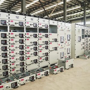
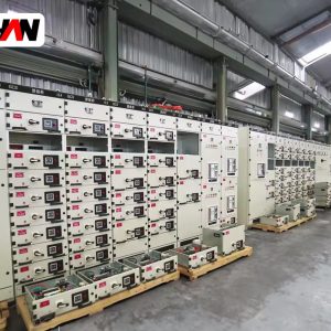
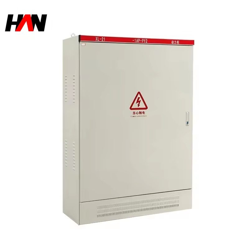
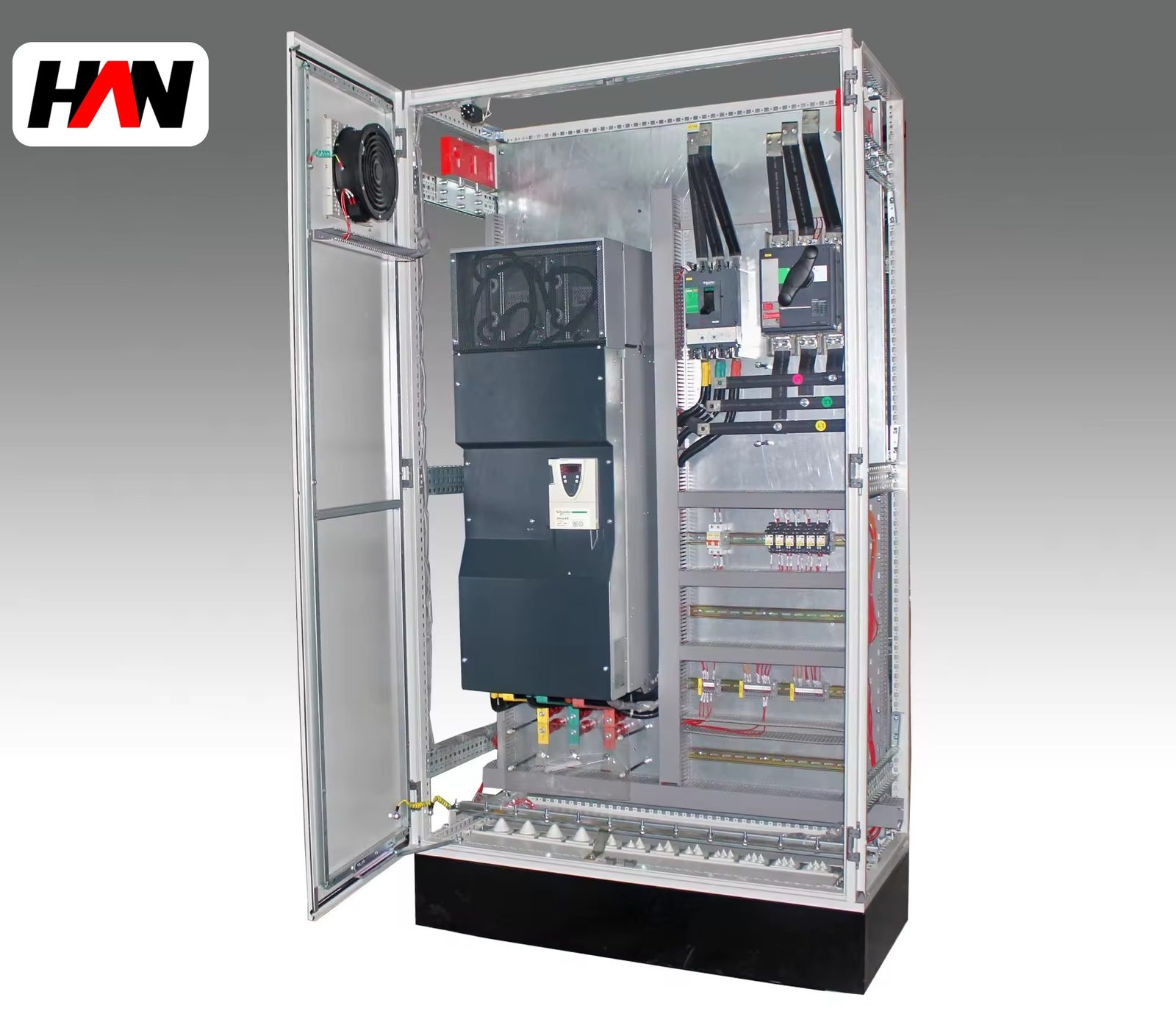
The dividing line is not the current alone; it is who opens the door and how much fault energy is behind it. A 125 A board in an apartment corridor belongs to the resident, and it must be safe to reset in the dark. A 250 A cabinet in a workshop belongs to the maintenance team, with a permit and a lock. Between those two worlds the equipment changes character, and specifications that blur the distinction produce either an over-engineered cupboard or an under-engineered switchroom.
Where it sits in the distribution chain
Follow the cable back from a socket: it lands on a miniature breaker in this board, the board is fed from a riser or a floor cabinet, that cabinet is fed from a main switchboard, and the switchboard from a transformer. Each step down reduces the current and the available fault energy, which is why a final board can be built from light materials and still be safe within its scope.
Typical homes are apartments, houses, shops, small offices, clinics, workshops and the tenant areas of commercial buildings. In each case the load is small, the circuits are numerous, and the person resetting a trip is not an electrician. That is the design brief, and every decision about ways, sensitivity and enclosure follows from it.
Selection and commissioning checklist
- Count the ways, then add spares. A board filled to the last position has no room for a future circuit and no room for heat.
- Apply the derating factors before choosing breaker ratings. Ambient, grouping and enclosure all push the usable current below the number printed on the device.
- Grade the residual current devices. A delayed or higher-threshold device upstream prevents one earth fault from blacking out the whole board.
- Match the device type to the load. Electronics and drives may need type A or type B rather than type AC.
- Keep neutral and earth separate downstream. A borrowed neutral defeats residual current protection and is one of the most common causes of nuisance tripping.
- Label every way and leave the schedule inside the door. The next person to open the board may not be the person who installed it.
Frequently asked questions
Why does the board trip when a single circuit faults?
Because the residual current device is shared. If one 30 mA device protects every way, any earth fault on any circuit trips it. Splitting the board into several residual current groups, or using one device per way, limits the outage to the faulty circuit.
Can a 125 A board feed a small three-phase motor?
It can carry a three-pole way within its rating, but a final board is not a motor control centre. Starting current, contactor duty and overload protection all belong to equipment designed for motor circuits; a miniature breaker alone does not provide them.
Is a plastic enclosure worse than a metal one?
Not inherently. An insulating enclosure gives good protection against accidental contact and does not corrode, but it transfers heat less readily and it must be selected with the temperature rise in mind. Metal enclosures need reliable protective bonding.
What does the 30 mA figure protect?
It provides additional protection against electric shock in circuits where a person may become part of the fault path. It supplements, and never replaces, earthing, bonding and the correct selection of circuit breakers.
How many spare ways should be left?
Enough for the loads the space is likely to gain, and enough to keep the rows from being packed end to end. A practical guide is one fifth of the ways, placed towards the ends of rows rather than in the middle.
Way count, incoming rating, enclosure material and the residual current arrangement are fixed per project, so the board is built to the circuit schedule rather than ordered as a fixed package. Send the schedule and the supply details and the configuration can be settled before delivery.