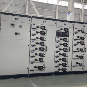
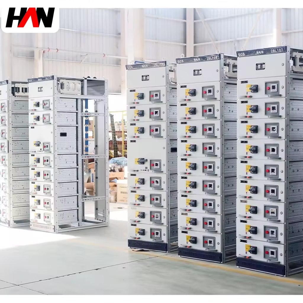
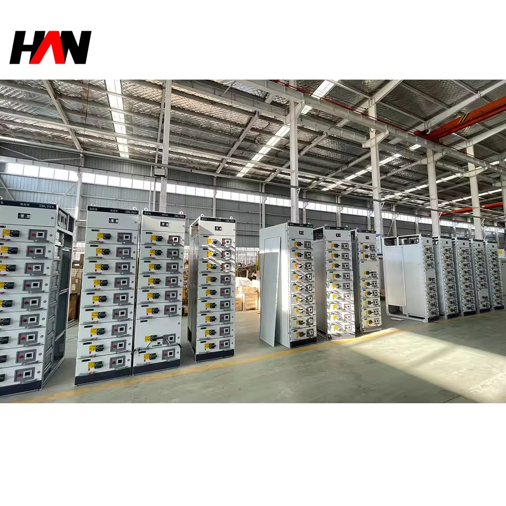
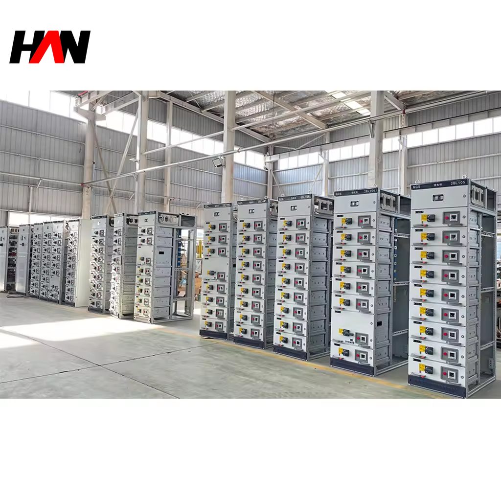
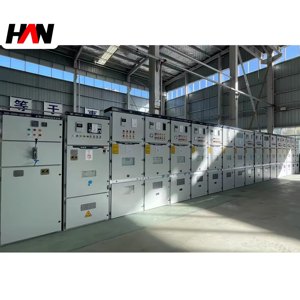
An MNS assembly is a low-voltage switchgear cabinet built from standard columns, standard compartment heights and standard withdrawable units, sized so that almost any combination of incoming, distribution and motor feeders can be assembled from the same catalogue of parts. The architecture is modular in two directions: columns bolt together to lengthen a board, and each column is divided into pockets on a 25 mm grid that accept units of a few fixed sizes. That is what allows a board rated at 6 300 A with a 100 kA short-time withstand to be extended, re-populated or repaired without redesigning the frame. This page explains the unit ladder, how very high currents are carried and cooled, what modularity actually buys a maintenance department, and where the approach costs more than it returns.
At a glance
| Rated operational voltage | 400 / 690 V AC |
| Main busbar current | up to 6 300 A |
| Short-time withstand, Icw | up to 100 kA, 1 s |
| Unit grid | E = 25 mm; 4E to 24E |
| Pocket formats | 8E/4, 8E/2, 8E full width |
| Internal separation | Form 2b to Form 4b |
| Degree of protection | IP31 – IP54 |
| Design standard | IEC 61439-1 and 61439-2 |
| Column widths | 400 / 600 / 800 / 1 000 mm |
Two words carry the whole idea
Modular here does not mean “made of panels”. It means that the load-bearing frame, the busbar system, the compartment dividers and the withdrawable units are all produced in a small number of standard sizes that interoperate. A column is a self-contained steel box with its own section of horizontal busbar and its own vertical distribution bars. Bolt four columns together and the busbar joint is a designed interface, verified once, rather than a one-off site fabrication.
Withdrawable means the functional unit travels. As in any draw-out design, the unit has connected, test and disconnected positions, and steel shutters close over the fixed contacts when it is withdrawn. The consequence for the standard is that the assembly is verified as a power switchgear and controlgear assembly to IEC 61439-2, with the additional requirement that the withdrawable part is treated as a component of the assembly whose insertion and withdrawal must not reduce the verified clearances, creepage distances or short-circuit strength.
The unit ladder, and why 25 mm matters
The vertical grid is a single module called E, 25 mm high. Every compartment height is a whole number of modules, and every unit is described by the height it occupies and the share of column width it takes. A small starter in a quarter-width pocket is an 8E/4 unit; the same 200 mm height split in two gives an 8E/2 unit; a full-width 200 mm compartment is an 8E unit. Taller devices take 16E or 24E, which is 400 mm or 600 mm of vertical space.
The arithmetic is unglamorous but it drives everything downstream. Because all heights are multiples of the same module, a column can be re-planned later without cutting steel: two 8E/4 pockets become one 8E unit, or an 8E unit plus a 16E compartment fills a 24E run. Standardisation also fixes the cable chamber and the vertical bar positions, so a unit can be swapped between columns of the same width without touching wiring. The visible benefit is a shorter bill of materials; the operational benefit is that a spare unit is interchangeable across every board of that type in a plant.
Ratings, and what each figure decides
| Parameter | Typical value | What it decides |
|---|---|---|
| Rated operational voltage, Ue | 400 / 690 V | Insulation level and device family |
| Rated insulation voltage, Ui | 690 / 1 000 V | Bar spacing and dielectric test level |
| Main busbar current | up to 6 300 A | Number of parallel bars and columns |
| Rated short-time withstand, Icw | up to 100 kA, 1 s | Fault level at the incomer, and support design |
| Rated peak withstand, Ipk | 2.1 × Icw at 50 Hz | Peak force on bars, joints and clusters |
| Unit current range | 1 – 630 A typical | Pocket width and cable termination space |
| Rated diversity factor | declared, 0.6 – 0.9 typical | Whether the busbar may be smaller than the sum of units |
| Form of internal separation | 2b to 4b | Which parts stay live when a unit is removed |
| Degree of protection | IP31 – IP54 | Ingress protection and the cooling strategy |
| Ambient temperature | −5 to +40 °C | Permitted rise and any current derating |
| Installation altitude | 2 000 m without correction | Cooling air density and dielectric margin |
| Column width | 400 – 1 000 mm | How many pockets fit side by side |
Read the current figures as a chain rather than a headline. 6 300 A is a busbar statement, not a promise about any single outgoing circuit: the incomer, the busbar and the vertical distribution bars each have their own limit, and the weakest of the three governs. Icw is declared for a stated duration, normally one second, and the protection clearing time has to fit inside it. Ipk then follows from Icw by the factor in IEC 61439-1, roughly 2.1 at 50 Hz and 2.2 at 60 Hz, because the asymmetry of a real fault current adds to the symmetrical value.
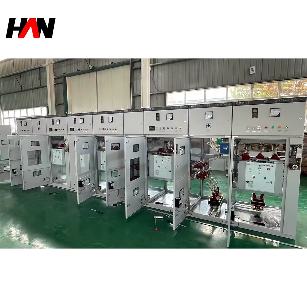
Engineering note. A modular low-voltage assembly is a 690 V class product, so a data sheet that lists it at 12 kV, 24 kV or 36 kV has borrowed a medium-voltage figure. Medium-voltage metal-enclosed switchgear to IEC 62271-200 uses vacuum or gas interruption, a much larger phase spacing and a completely different busbar; it is not the same cabinet with a thicker door. When a project asks for both voltage classes, expect two separate assemblies and two separate verification files.
Carrying 6 300 A and surviving 100 kA
Heat is the first constraint at high current. A conductor carrying I dissipates I squared times R per unit length, so doubling the current multiplies the heat by four while the surface available to radiate it grows only with the perimeter. Above roughly 3 200 A the bar set is usually split into two or more parallel paths per phase, spaced to leave a cooling channel, and the columns above the incomer are given either enlarged vents or forced ventilation. Alternating current also crowds toward the surface of a conductor and redistributes between parallel bars, so the effective resistance of a wide stack is higher than its direct-current value would suggest.
Mechanical stress is the second. The force between two parallel bars is proportional to the square of the current and inversely proportional to their spacing, and it reverses with the current, so at 50 Hz the bar set is pushed and pulled a hundred times a second during a fault. A 100 kA withstand corresponds to a peak near 210 kA, and the supports have to hold that without permanent deformation while the bars themselves stay straight enough to keep their clearances. Insulating supports are spaced closer together on high-fault boards, which is why a 100 kA column looks denser inside than a 50 kA one of the same width.
The thermal limit of the assembly is expressed as a temperature rise above ambient, not an absolute temperature, in IEC 61439-1. That detail decides site reality: a board verified in a 35 °C mean ambient has no margin left in an uncompressed plant room at 50 °C, and either the current has to come down or the ventilation has to improve. Adding a fan is not automatically the answer, because a fan that draws unfiltered air also draws dust onto insulating surfaces.
What modularity buys a maintenance department
The commercial case for a standard unit ladder is spares. Instead of holding one of every starter the plant has ever bought, a site holds a small set of configured units at the common sizes and swaps them between feeders. Since the units are interchangeable within a type, a failed 30 kW starter becomes a half-hour job: isolate, withdraw, insert the spare, restart. The failed unit is repaired on a bench, where the work is cheaper and the test equipment is better.
Expansion works the same way. Empty pockets fitted with shutters and tap-offs can be populated years later, and an extra column can be bolted to the end of a board with a designed busbar joint. That is a different proposition from a welded, one-off frame where added circuits mean a new section and a shutdown. The discipline the design demands is that the original order leaves spare pockets and that the unit schedule is documented, because a modular board with no drawing is just a cabinet with expensive hardware inside.
Comparing it with other low-voltage constructions
| Criterion | Modular withdrawable | Draw-out, single grid | Fixed |
|---|---|---|---|
| Highest busbar current | 6 300 A with parallel bar sets | Around 4 000 A | Around 3 150 A |
| Smallest unit granularity | 8E/4, four starters across one row | Full-width drawers only | No unit; devices on a plate |
| Spare-part strategy | One unit family across boards | Spares per section size | Spares per device |
| Cost per outgoing circuit | Highest: frames, guides, clusters | High | Lowest |
| Best fit | Large boards with mixed feeders and staged growth | Motor control centres of moderate size | Distribution, capacitor and lighting duty |
The three columns are not a quality ranking. A fixed board is the honest choice for a capacitor bank or a lighting distribution point, where nothing will ever need to be swapped live. The modular design earns its price where circuits are numerous, feeders differ, and downtime is measured in production loss.
Where it sits in a distribution chain
A board of this type usually sits immediately downstream of the main transformer, where the current is highest and the fault level is worst. From its busbar, feeders serve sub-distribution boards, large drives and motor control centres further out. The 6 300 A rating exists precisely for that first step: two transformers running in parallel, or a single large unit feeding a process with a concentrated load. Downstream, the same column design continues as a motor control centre at lower current.
Sectors that specify modular withdrawable boards tend to be the ones with continuous process and long equipment lives: water and wastewater, cement and minerals, pulp and paper, automotive lines, food and beverage, and the electrical rooms of large commercial and infrastructure projects. The common thread is not the industry but the maintenance policy: these are sites that intend to keep the board for twenty years and modify it while running.
Selection and commissioning checklist
- Start from the fault study. Choose Icw with margin over the prospective current at the incomer, then confirm the declared duration is longer than the clearing time of the upstream device.
- Decide the diversity factor before the busbar. Total connected load is not operating load, and the busbar may be sized on a declared factor, but that declaration has to match how the plant actually runs.
- Plan the unit schedule in modules. A column that ends with 4E of unusable height is a planning error, not bad luck.
- Order spare pockets complete. Shutters, tap-offs and vertical bar stubs cost little at build time and a great deal afterwards.
- Match ventilation to the room. High-current columns need airflow, and the filters, if any, need a maintenance routine that someone actually follows.
- Keep the verification file. Design verification, routine test records and the unit schedule are what make a modular board maintainable a decade later.
Frequently asked questions
Can a 6 300 A board really be built from standard columns?
Yes, by using several parallel bar paths per phase and a matching number of columns at the incomer. The rating belongs to the verified busbar arrangement, not to a single column, so the incomer section is always a specific design rather than a catalogue item.
What does the 8E in 8E/4 mean?
The first figure is height in modules of 25 mm, so 8E is 200 mm. The second says how many units share that height across the column width. An 8E/4 pocket therefore holds one unit 200 mm high and roughly a quarter of the column wide.
Is IP54 compatible with high current?
It is, but not free of charge. A sealed enclosure traps heat, so the verified current for the same bar set drops, or forced ventilation with a heat exchanger is added. Specify the current and the IP rating together and ask for the temperature-rise evidence for that combination.
How often should withdrawable units be exercised?
There is no universal interval, but leaving a mechanism untouched for years is worse than using it. A planned operation of each unit during a shutdown, together with a check of shutter movement and cluster condition, keeps the mechanism free and reveals wear early.
Can fixed and withdrawable columns be mixed in one board?
Frequently yes, within one verified system, because the columns share a busbar interface. The mixed arrangement is normal in practice: withdrawable units where circuits must be restored quickly, fixed compartments for large incomers or capacitor duty.
Column count, unit schedule, fault level and form of separation are set per project, so the layout is built to the single-line diagram rather than to a fixed catalogue number. Send the diagram and the fault study and the arrangement can be fixed before steel is cut.