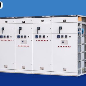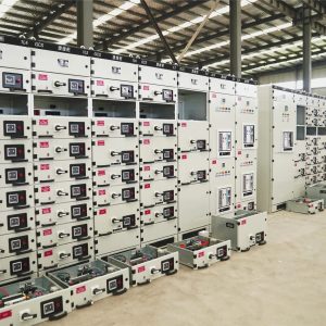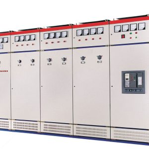
An XL-21 cabinet is a single, closed, front-access power distribution box for 380 V and 400 V systems, sized from about 100 A to 630 A, standing on the floor or hung on a wall. It is the piece of equipment that sits between a plant’s main switchboard and the everyday loads: a workshop’s sub-distribution, a pump room, a small compressor house, a floor of a commercial building. It has one door, one mounting plate, a busbar at the top and cable entry at the bottom. This page explains what the type designation covers, how the enclosure is laid out, where the IEC 61439 boundaries fall for a board of this size and who is allowed to operate it, and how to tell when a job needs this cabinet rather than a larger assembly.
At a glance
| Rated operational voltage | 230 / 400 V AC |
| Rated current | 100 – 630 A |
| Outgoing ways | 4 – 12 typical |
| Short-time withstand, Icw | 10 – 25 kA, 1 s |
| Mounting | Floor standing or wall mounted |
| Internal separation | Form 1 or Form 2 |
| Degree of protection | IP30 – IP54 |
| Design standard | IEC 61439-1, with -2 or -3 as applicable |
| Location | Indoor, dry, ventilated rooms |
What the designation stands for
XL-21 is a regional type reference for an indoor AC low-voltage power distribution cabinet, and the number is a design sequence rather than a rating. In practice the name describes a format: a single-section, single-front, enclosed cabinet with devices mounted on a plate behind a hinged door, cable entry at the bottom, and a busbar system at the top or along the rear. It is the smallest format that can still take a moulded-case breaker of a few hundred amps with room for lugs.
The important distinction is scale, not style. A GGD-type fixed assembly is built as a row of sections with a busbar running the length of the row and separate chambers for the busbar, the devices and the cables. An XL-21 is a single enclosure where the same three zones exist but share one volume. That difference decides how much current can be handled, how much separation is possible, and whether the board can be extended later without replacing it.
Inside the enclosure
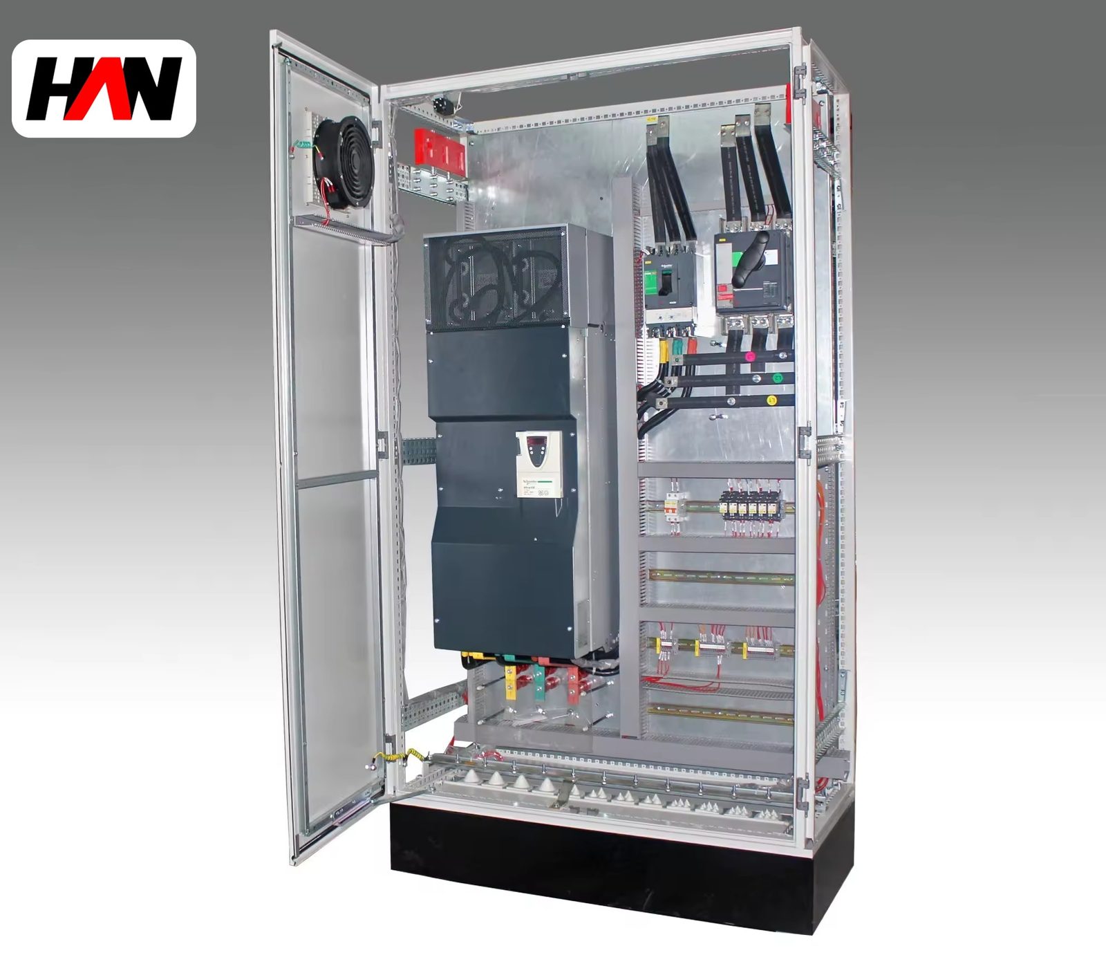
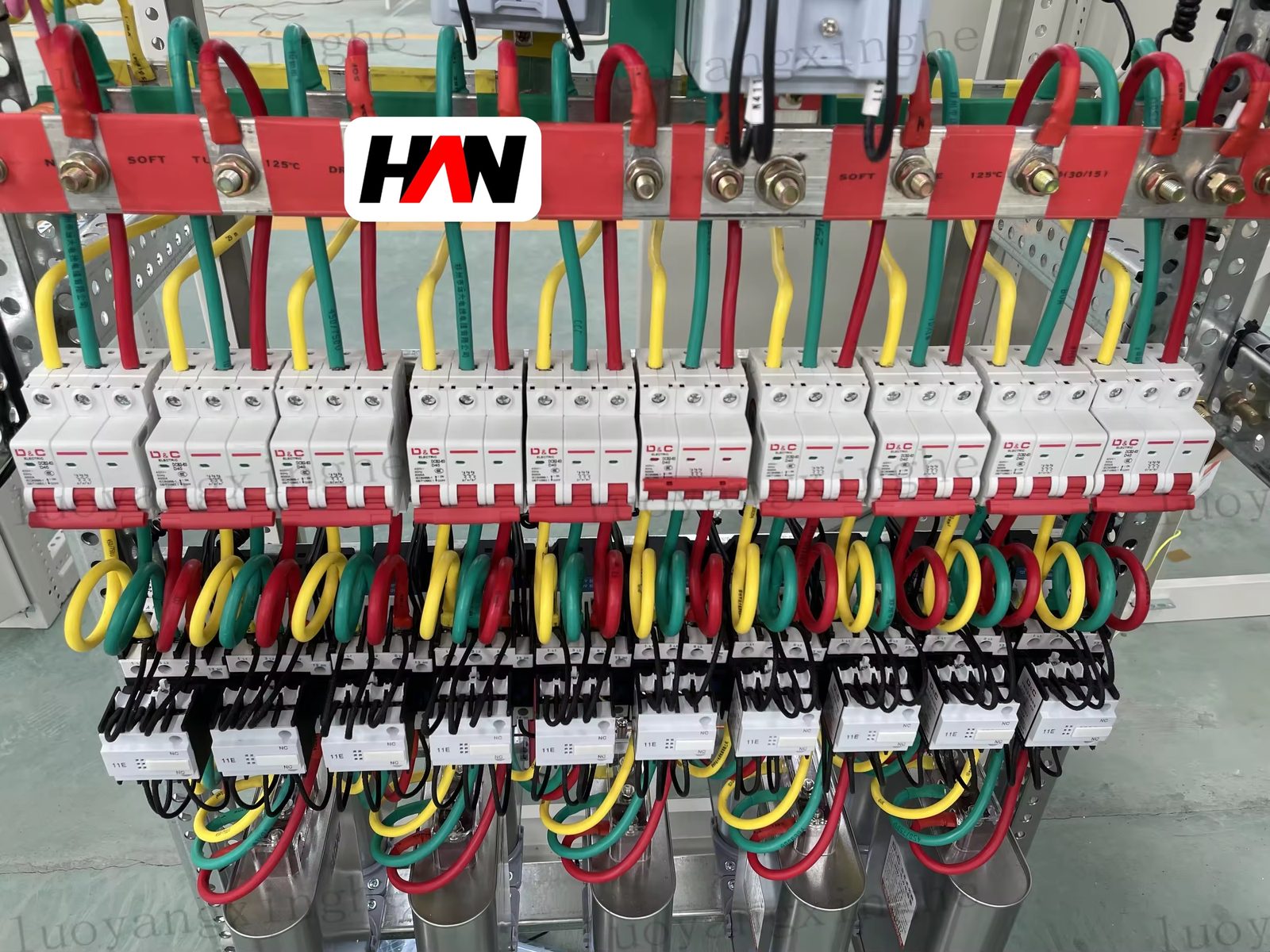
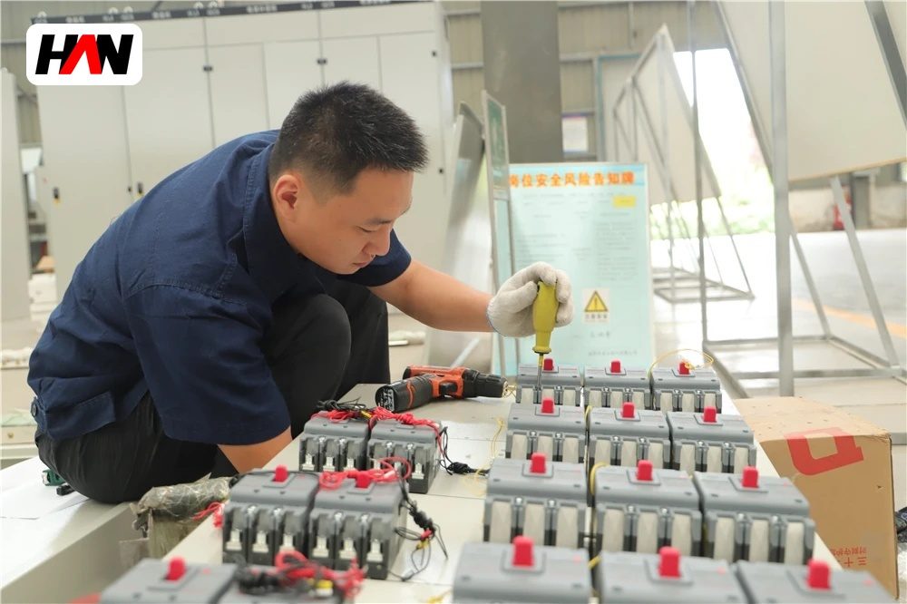
Devices sit on a galvanised plate bolted to the frame, in one or two rows. Incoming and outgoing breakers face the same way, which is why a small cabinet can look crowded: there is no cable chamber, only the space behind and below the plate. Cable entry is a removable gland plate at the bottom, and the depth of the enclosure has to leave room for a bending radius that will not strain a 240 mm² lug. Where that space runs out, installers bend conductors tighter than the cable maker allows and the terminal heats up.
The frame is normally 1.5 mm to 2.0 mm cold-rolled sheet, with a powder-coated finish and a gasket on the door for the higher ingress ratings. Small ratings are often supplied with wall brackets; from roughly 250 A upward, the weight of the breakers and the stiffness of the incoming cables make a floor-standing version the practical choice. Height sits near 1 700 mm to 2 000 mm for the floor type, with width and depth varying by way count.
Ratings and what each one limits
| Parameter | Typical value | What it limits |
|---|---|---|
| Rated operational voltage, Ue | 230 / 400 V | Single-phase and three-phase outgoing circuits |
| Rated insulation voltage, Ui | 500 / 690 V | Clearances between devices and bars |
| Rated current of the incomer | 100 – 630 A | Busbar section and cable terminal size |
| Short-time withstand, Icw | 10 – 25 kA, 1 s | Fault level the busbar can hold |
| Rated peak withstand, Ipk | 2.1 × Icw at 50 Hz | Bar supports and device mounting stiffness |
| Outgoing device type | MCCB or MCB, per IEC 60947-2 | Selectivity with the incomer |
| Form of internal separation | Form 1 or 2 | Whether maintenance means a full shutdown |
| Degree of protection | IP30 – IP54 | Dust and water ingress, defined in IEC 60529 |
| Ambient temperature | −5 to +40 °C | Rated current, through the temperature rise limit |
| Pollution degree | 3 | Creepage distance for a workshop environment |
| Enclosure sheet | 1.5 – 2.0 mm steel | Stiffness under fault and handling wear |
A 630 A rating in a single enclosure is not a comfortable number. The busbar is short, which helps, but the heat from a 630 A incomer, several outgoing breakers and the cable lugs all has to leave through one sheet-steel box with a modest surface area. The declared current is therefore tied to a declared ambient and a declared way count. A cabinet passed for 630 A with four outgoing ways will not carry 630 A with a full plate of loaded breakers unless the temperature-rise verification says it does.
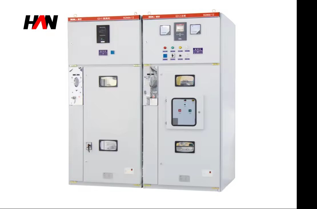
Engineering note. Two labelling habits cause trouble with cabinets of this size. The first is the old 380 V nominal, which circulates because national practice used 380/220 V before harmonisation; IEC 60038 lists 230 V phase-to-neutral and 400 V phase-to-phase as the standard values for these systems, and equipment marked 380 V is simply being described in the older convention. The second is a medium-voltage figure such as 12 kV attached to a low-voltage cabinet. A 690 V class assembly cannot be a 12 kV product; that requirement belongs to metal-enclosed switchgear to IEC 62271-200.
Which part of IEC 61439 applies, and who may open the door
Part 1 of IEC 61439 applies to every assembly and is never optional. The part that follows depends on the duty. Part 2 covers power switchgear and controlgear assemblies and is the right reference for a cabinet whose circuits are operated by instructed or skilled persons. Part 3 covers distribution boards intended to be operated by ordinary persons, and its scope is deliberately bounded on voltage and on the rated current of the incoming circuit, which is why a 400/230 V board with a modest incomer can be a Part 3 product while the same enclosure at 630 A cannot.
The practical meaning of that boundary is about people, not hardware. A distribution board to Part 3 is designed so that an unskilled person can reset a device or replace a fuse without meeting a live part, and it carries the markings and warnings that go with that assumption. Above the scope of Part 3, the assembly is a Part 2 product: it assumes a locked electrical room, a permit system and someone who knows what an arc looks like. Selling a 630 A cabinet as though it were a domestic board is a documentation error with real consequences.
Form of separation follows the same logic. A single-volume enclosure is normally Form 1, where no internal barrier separates functional units, or Form 2, where busbars are separated from the functional units but the units are open to each other. Nobody should plan live work inside a Form 1 cabinet: isolating the incomer is the only defensible procedure, and that means the loads on the board go down with it.
Heat and fault current in a small box
Heat leaves a cabinet by convection over the outer surfaces and by radiation, and the surface area of a small enclosure is not generous. Losses rise with the square of the current, so the last 100 A of a 630 A rating costs far more heat than the first. That is why the same enclosure is offered with different current ratings depending on way count and ventilation: the physical box does not change, the verified thermal case does.
Fault current inside a single volume behaves differently from a compartmented board. There is no barrier between the busbar and the outgoing terminals, so an arc at one outgoing device is an arc in the same air volume as the incomer. IEC 61439 does not require an internal arc test, and IEC/TR 61641 offers guidance for those who want one. For a board mounted in a corridor outside a workshop, that is worth a conversation with the person who will operate it.
The fault level itself is usually modest at this point in the system. Cable impedance between the main board and the cabinet reduces the prospective current, which is why a 10 kA to 25 kA busbar is often adequate where the upstream board is rated 50 kA. That reduction is a calculation, not an assumption: it depends on cable length, conductor size and the source impedance, and it must be written down.
Where the boundary sits against larger and smaller boards
| Criterion | Single-door cabinet | Multi-section fixed board | Final board |
|---|---|---|---|
| Incoming current | 100 – 630 A | 630 – 3 150 A | Up to 125 A |
| Separation | Form 1 or 2 | Form 1 to 4 | Single volume, insulating parts |
| Operation by ordinary persons | Not intended | Not intended | Designed for it within Part 3 scope |
| Extension | Replace, or add a second cabinet | Add a section to the busbar run | Add ways if space allows |
| Typical home | Workshop, pump room, floor distribution | Main switchroom, plant distribution | Apartment, office area, small shop |
Read the three columns as steps on one chain, not as competitors. Power enters a multi-section board, leaves through a feeder to a cabinet of this type, and leaves that cabinet again through smaller circuits toward final boards. Each step reduces current and fault level, and each step can afford less separation and less instrumentation. Choosing equipment one size too large wastes money; one size too small means the next extension turns into a rebuild.
Where it belongs
The cabinet earns its place wherever a small, defined group of loads needs its own isolation point: a machine shop with a handful of three-phase outlets, a pump set with two duty and one standby unit, a compressed air room, a small packaged plant, a floor of an office building feeding lighting and socket final boards. It is also common as a dedicated control and distribution point for a single process unit, where the operator wants one switch to kill everything on that unit.
It is the wrong choice in a dusty or wet environment, in a location where the door will be opened by people without electrical training, or where the fault level at the terminals is above its declared withstand. None of those are exotic conditions, which is why the nameplate and the ambient rating deserve more attention than the paint colour.
Specification and commissioning checklist
- Calculate the fault level at the cabinet, not at the main board. Cable impedance reduces it, and the reduced value is what the busbar and the outgoing devices have to withstand.
- Declare the way count with the current. A 630 A rating assumes a particular load pattern; ask for the temperature-rise case that goes with the plate you are ordering.
- Leave cable space. Depth and gland plate position decide whether a large lug can be terminated without over-bending the conductor.
- Fix the mounting method early. Wall brackets, floor plinths and cable trench positions are decided before the wall is built, not after.
- Confirm the standard and the intended operator. Part 2 and Part 3 assemblies carry different assumptions about who opens the door, and the documentation should say which one applies.
- Test at the works. Insulation resistance, dielectric withstand, protective bonding continuity and a functional check of every breaker and interlock before the cabinet leaves.
Frequently asked questions
Is 380 V the same as 400 V?
They describe the same kind of system in different conventions. IEC 60038 sets 230 V phase-to-neutral and 400 V phase-to-phase as standard values; 380/220 V is the older national practice still used in some documents and nameplates. A cabinet marked 380 V is built for the same nominal system, but the design should be checked against the actual supply voltage.
Can two cabinets be coupled to make a bigger board?
They can be installed side by side and fed from a common feeder, but they remain two assemblies, each with its own verification. A genuine multi-section board shares one busbar system and is verified as a single assembly, which is a different product.
What does Form 2 add over Form 1?
Form 2 puts a barrier between the busbars and the functional units, so the busbar is not exposed when a device compartment is opened. It does not separate the units from one another, and it does not make the board safe for live work.
Is IP54 necessary indoors?
Only where dust or water spray is present. A higher IP rating traps heat and reduces the current the cabinet can carry, so a clean, dry room is better served by IP30 or IP41 with adequate ventilation than by a sealed box that runs hot.
Can the cabinet be installed outdoors under a canopy?
A standard indoor cabinet is not designed for it. Rain driven at an angle, condensation and ultraviolet exposure all attack a light-gauge enclosure, and the correct answer is an outdoor enclosure or a small prefabricated substation that gives the equipment a controlled climate.
Way count, incoming current, fault level and mounting arrangement are set per project, so the cabinet is configured to the load schedule rather than ordered from a fixed list. Send the schedule and the supply details and the arrangement can be confirmed before the sheet is cut.