A transformer built to the ANSI and IEEE family of standards is a different animal from one built to IEC 60076, even when both are three-phase, oil-immersed and bolted to the same concrete pad. The two systems grew out of separate distribution practices, and the differences run through voltage class naming, insulation levels, temperature rise, how the winding connection is declared and how a bid is evaluated. A buyer comparing a 500 kVA unit from each side of that divide is often comparing two differently stressed machines with the same number on the label. This page sets out what the ANSI designation means, how the magnetic and electrical construction is arranged at these small ratings, what each figure on the nameplate governs, and why two quotations for the same apparent duty can sit far apart without either supplier being dishonest.
At a glance
| Rated power | 30 – 500 kVA |
| High-voltage class | 13.2 / 13.8 / 34.5 kV |
| Low-voltage | 208Y/120, 240, 480Y/277 V |
| Frequency | 60 Hz |
| Basic impulse level | 95 kV at 15 kV class, 150 kV at 34.5 kV class |
| Average winding rise | 65 K, 80 K hot spot |
| Ambient basis | 30 °C average, 40 °C maximum |
| Taps | Two 2.5 % above, two below |
| Standards | IEEE C57.12.00, C57.12.90, C57.12.20 |
What “ANSI type” describes, and what it does not
There is no single ANSI transformer. The label is shorthand for a design verified against a family of standards, chiefly the IEEE C57.12 series, which in turn grew out of the older ANSI C57 documents. C57.12.00 carries the general requirements — rating structure, temperature rise, insulation levels, tolerance on impedance and losses, and the rules for nameplate data. C57.12.90 is the test code, the document that says how ratio, resistance, impedance, no-load loss, load loss, applied voltage and impulse withstand are actually measured and what counts as a pass. C57.12.20 covers the overhead-type distribution units rated 500 kVA and below at voltages up to 34.5 kV, which is precisely the band this page describes. Where a unit is built into an enclosure for underground distribution, C57.12.34 takes over the enclosure and compartment requirements.
Read the label as a scheme of assumptions. The ANSI scheme assumes 60 Hz, a defined set of distribution voltage classes, a temperature rise measured against a 30 °C average ambient, and a preference for simple, robust, single-ended designs that a line crew can install from a bucket truck. The IEC scheme assumes 50 or 60 Hz, a wider ladder of system voltages, and a temperature rise measured against a 40 °C maximum ambient with a 20 °C annual average. Neither is better. They answer different questions about what a network looks like.
Construction and the magnetic circuit
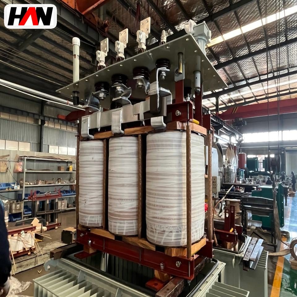
At 30 to 500 kVA the magnetic circuit is the part that differs most from a European-style design. Two arrangements dominate. A stacked core is built from rectangular laminations interleaved at the corners, with mitred joints to keep the flux path tight; it is mechanically stiff and straightforward to wind. A wound core is formed by winding a continuous strip of grain-oriented steel into a closed rectangle and then annealing it, which keeps the grain aligned along the flux path in every limb and corner. Wound cores cut no-load loss and run quieter, at the cost of a more delicate assembly and a winding operation that has to thread the coil onto the core.
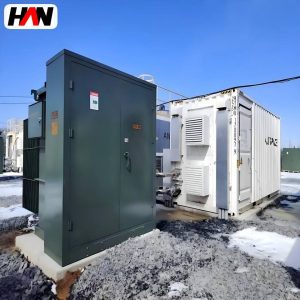
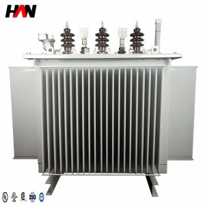
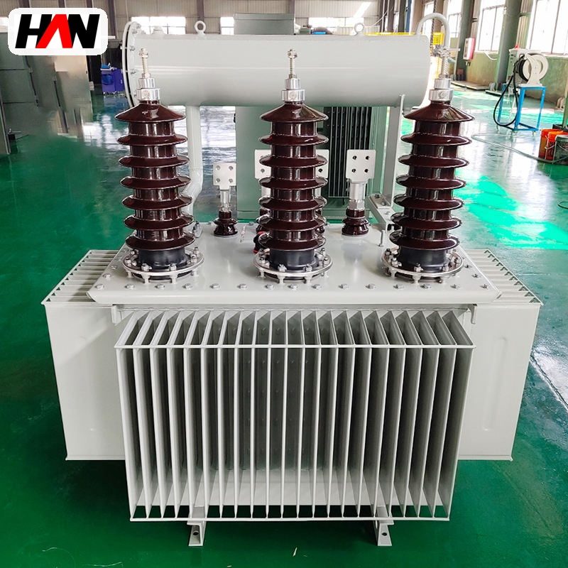
Both arrangements are usually core-form at these ratings: the winding surrounds the core limb, low voltage inside, high voltage outside. The tank is welded steel, either round or rectangular, with cooling panels or radiators welded to the walls. Bushings on a 15 kV class unit are small porcelain or epoxy cones; on a 34.5 kV class unit they grow noticeably, and that growth is one of the reasons a 34.5 kV transformer costs more than the same kVA at 13.8 kV. Where the unit is mounted on a pole these bushings are open to the air and live, which is acceptable because nobody stands at that height. Move the same transformer into a pad-mounted enclosure at pavement level and the terminations have to become dead-front — conducting parts buried in solid insulation, cable connected through a separable elbow — because the switching point is now within reach of the public.
The high-voltage winding on a 13.2 kV or 13.8 kV distribution unit is normally delta connected, and the low-voltage winding is star connected with the neutral brought out. That combination keeps zero-sequence current out of the primary network while giving the secondary a solid neutral for single-phase loads and a return path for earth fault current. Because ANSI practice declares the connection differently from IEC practice, the nameplate shows a connection diagram and a polarity marking rather than a clock number. Polarity is described as additive or subtractive, a convention inherited from single-phase practice that tells a lineman how the secondary voltage relates to the primary at the terminals when the unit is paralleled or banked.
Ratings, and what each figure governs
On an ANSI nameplate the voltage is usually given as a class and a ratio, and the insulation as a single impulse level. Those two conventions carry more information than they appear to.
| Parameter | Typical value | What it governs |
|---|---|---|
| Rated power | 30 – 500 kVA | Continuous secondary current at rated voltage |
| Voltage class | 15 kV, 25 kV, 34.5 kV | Bushing length, clearance and the impulse level that follows |
| Basic impulse level | 95 kV, 125 kV, 150 kV | Insulation thickness and winding end clearances |
| Rated frequency | 60 Hz | Core area for a given voltage per turn |
| Percent impedance | Low single figures on distribution sizes | Secondary fault current, voltage dip and parallel load sharing |
| No-load loss | Guaranteed value, tested per C57.12.90 | Standing cost, and the A factor used in bid evaluation |
| Load loss at rated current | Referenced to a stated winding temperature | Copper section and the B factor in bid evaluation |
| Temperature rise | 65 K average, 80 K hot spot | Insulation life and usable overload margin |
| Taps, de-energised | 2 × 2.5 % above and below | Correction for a feeder that runs high or low |
| Winding material | Copper or aluminium | Conductor section for the same loss, and the mass to be supported |
| Cooling class | ONAN, self-cooled | How much heat the tank surface must reject unaided |
| Polarity | Additive or subtractive | Whether two units can be banked or paralleled |
The impulse level deserves a plain explanation, because it is the number buyers skip. A lightning strike arriving along an overhead line produces a voltage spike measured in microseconds, not the steady sine wave the transformer was designed around. Insulation that survives the sine wave can still puncture under that spike, because the stress distribution across a winding is capacitive rather than resistive during a fast front. Basic impulse level is the crest value of a standard 1.2 by 50 microsecond wave that the insulation must withstand in test. It sets how much paper, oil and clearance is built into the winding ends and how long the bushings are. A 95 kV level suits a 15 kV class system; 150 kV suits 34.5 kV. Buying a 34.5 kV unit with a nominal 95 kV level to save money is not a bargain, it is a unit that will fail on the first nearby strike.
Engineering note. Class and ratio are not the same information. A 34.5 kV class unit may be connected 34 500 GrdY / 19 920 V, where 19 920 is the line-to-neutral value obtained by dividing 34 500 by the square root of three. That grounded-wye primary is common on North American feeders because it allows a cheaper insulation design on the primary and gives the utility a measurable earth reference. A delta-connected 34.5 kV primary is a different product with different insulation duty, and the two are not interchangeable on the same feeder. Confirm the connection diagram before the order, not after the unit arrives.
Heat, loss and what the ambient basis hides
Loss splits into the same two components everywhere: core loss that is present as soon as the unit is energised, and winding loss that climbs with the square of the load. What changes between standards is the assumed ambient against which temperature rise is judged. The ANSI basis is a 30 °C average ambient with a 40 °C maximum, and a 65 K average winding rise with an 80 K hot spot on top of it. The IEC basis uses a 40 °C maximum and a 20 °C annual average for its 65 K figure. Because the two are measured from different starting points, a unit that satisfies one set of numbers is not automatically equivalent to a unit that satisfies the other, even when both carry the same kVA and the same rise in kelvin.
Insulation ageing follows the hot spot, not the average. Cellulose in oil degrades faster as temperature climbs, and the widely quoted industry rule of thumb says the reaction rate doubles for each additional 6 K at the hot spot. It is an empirical approximation rather than a clause in C57.12.00, and it is used to explain why a sustained overload in a 45 °C summer is more expensive than the same overload in winter. Practical reading: a unit rated 65 K rise and installed where the daily average sits well above 30 °C is already consuming part of its life margin before any overload is applied.
Fault behaviour is the second half of the thermal story. A short circuit on the secondary produces a current limited mainly by the transformer’s own impedance, and that current produces magnetic forces between winding turns proportional to the square of its peak value. Small distribution units are built to withstand the mechanical duty of a through-fault for the short time the protection takes to clear, and repeated through-faults accumulate fatigue in the winding support structure. This is why the same kVA with a lower impedance is not simply better: it delivers a stiffer supply, and it also delivers a larger fault current to the low-voltage equipment and to its own windings.
Why two quotes for the same kVA differ
A purchase engineer who receives one figure at 480Y/277 V, 95 kV BIL, 65 K rise and another at the same kVA but 34.5 kV class, 150 kV BIL and a different loss guarantee may be looking at a spread that no negotiation will close. The table lists where the money goes.
| Cost driver | Effect on price | How to check it |
|---|---|---|
| Voltage class and BIL | Rises steeply from 15 kV to 34.5 kV class | Compare class and impulse level, not just the ratio |
| Loss guarantee | Lower guaranteed loss costs more core and copper | Ask for guaranteed P0 and Pk, with tolerance, in writing |
| Temperature rise | A 55 K rise design costs more than 65 K for the same kVA | Look for a second rating, such as 55/65 K dual rated |
| Impedance | Non-standard values need a different winding geometry | Check the tolerance band as well as the nominal figure |
| Winding material | Aluminium is cheaper, but needs more section for equal loss | Judge on the loss figures, not on the metal named |
| Enclosure and finish | Painted tank, galvanising, tamper-resistant covers all add cost | Match the corrosion category and the site’s access rules |
| Tests and documentation | Routine tests, impulse tests and witnessed tests each add hours | List the tests you require in the enquiry, per C57.12.90 |
Utilities in North America rarely buy on price alone. A bid is scored on total evaluated cost, in which the guaranteed no-load and load losses are multiplied by capitalised loss factors — an A factor for no-load loss, a B factor for load loss — and added to the purchase price. Two units at the same kVA can therefore rank in either order depending on those factors. A supplier who knows the evaluation is coming will offer a lower-loss design at a higher price and win. A supplier who is asked only for the cheapest conforming unit will offer exactly that, and the losses will be higher. Neither behaviour is unusual; they are answers to different questions.
Where the unit sits in a distribution chain
In a North American arrangement the chain usually starts at a feeder recloser or a fused cutout on a 15 kV or 34.5 kV circuit. From there, overhead units are pole mounted on a platform or hung from a bracket, and underground units go into a pad-mounted enclosure at grade. The secondary runs to a meter and then to a service panel. A single 500 kVA unit might serve a small industrial customer, a strip of shops, a farm irrigation set or a cluster of houses, which is why the 30 to 500 kVA band is where most utility transformer purchasing happens.
Downstream equipment sets two constraints on the transformer. The service equipment’s interrupting rating has to exceed the fault current the transformer can deliver, and the voltage drop at the end of the run has to stay inside the limits the local code imposes. Both improve with a lower impedance, and both cost money in switchgear when the impedance is chosen too low. Upstream, the fuse or recloser has to coordinate with the transformer’s inrush, which is many times rated current for a fraction of a second on energisation, and with its through-fault capability.
Selection and commissioning checklist
- Read the class before the ratio. Confirm that the voltage class and the impulse level match the feeder, then confirm the connection diagram.
- State the secondary configuration. A 480Y/277 V service and a 480 V delta service need different windings. Writing only “480 V” leaves the choice to the factory.
- Ask for guaranteed losses with tolerances. Tested values are compared with guarantees under C57.12.90, and the tolerance band matters as much as the nominal figure.
- Confirm the rise basis if the site is hot. A unit rated on a 30 °C average ambient in a location that averages 38 °C will run derated, and asking for a 55 K rise design is cheaper than discovering it later.
- Match the finish to the atmosphere. Coastal and industrial air need a heavier coating system and, on pad-mounted units, sealed compartments with corrosion-resistant hardware.
- Agree the tests before the order. Resistance, ratio, polarity, no-load loss, load loss and impedance are routine; impulse and temperature rise are type or special tests and should be named explicitly if required.
- Check the physical envelope. Pad, clearance to walls, bushing height on a 34.5 kV unit and the crane or boom access all constrain a replacement as much as the electrical rating does.
Frequently asked questions
Is an ANSI transformer the same as an IEC transformer with different paperwork?
No. The insulation levels, the ambient basis for temperature rise, the tap arrangement, the way the winding connection is declared and the loss evaluation practice all differ. A unit built to one scheme can usually be adapted to the other, but it is a design change rather than a label change.
Can I use a 50 Hz unit on a 60 Hz feeder?
Running a 50 Hz design at 60 Hz at the same voltage is generally safe, because the higher frequency lowers flux density in the core. The output voltage rating then has headroom that the nameplate does not claim, but the losses and the impedance change slightly. Running a 60 Hz design at 50 Hz is the case to avoid.
Why does a 34.5 kV unit cost so much more than a 13.8 kV one at the same kVA?
Insulation. The impulse level rises from 95 kV to 150 kV, which thickens the winding insulation, lengthens the bushings, widens clearances and grows the tank. Core and copper are roughly the same; the dielectric system is not.
What does additive polarity mean in practice?
It describes how the secondary voltage adds to or subtracts from the primary when the terminals are referenced the same way. It matters when units are banked or paralleled, because the wrong combination produces a large circulating current instead of a shared load.
How much overload can the unit take?
More than its nameplate for short periods, because the thermal time constant of oil and windings is measured in hours rather than seconds. Sustained overload, however, spends insulation life that cannot be recovered. Where overload is expected as normal duty, buy the next size up rather than plan on the margin.
Voltage class, ratio, connection, impedance, loss guarantee and finish are fixed per order, so a unit can be built to a specific feeder rather than to the nearest catalogue line. Send the system voltage, the required secondary configuration and the load profile, and the electrical specification can be settled from those three.