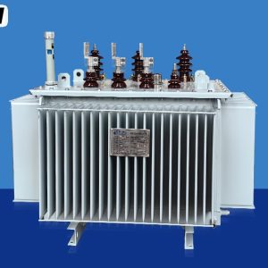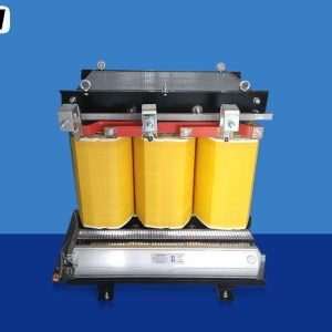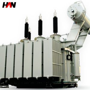
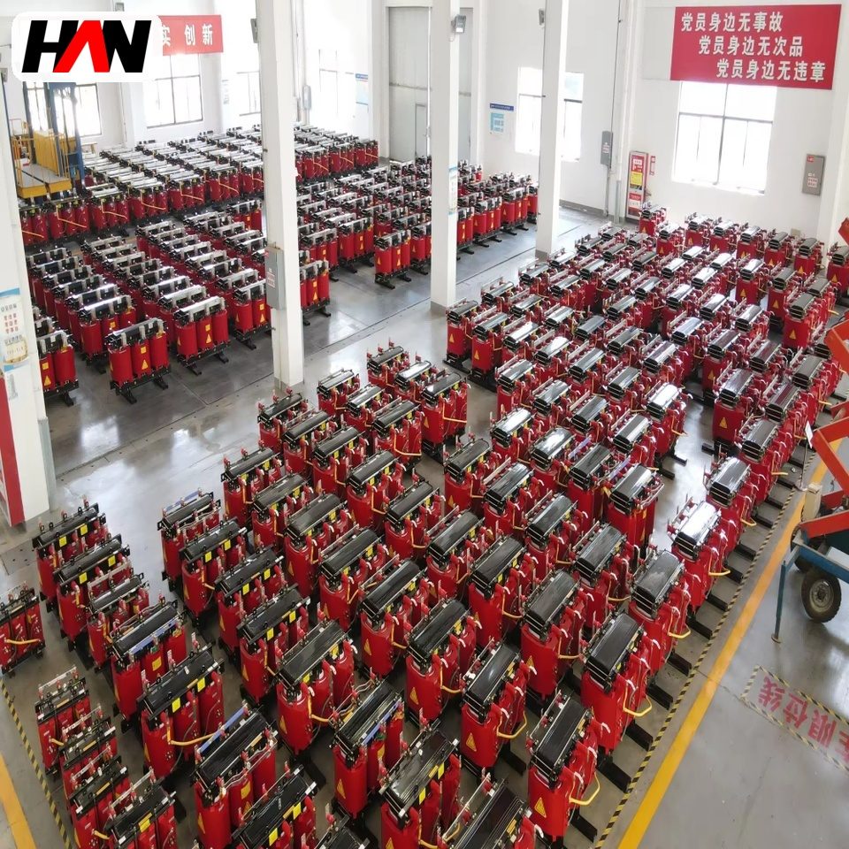
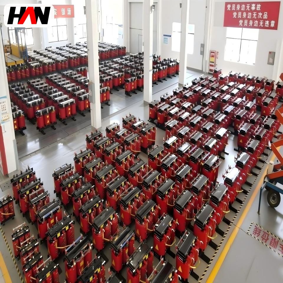
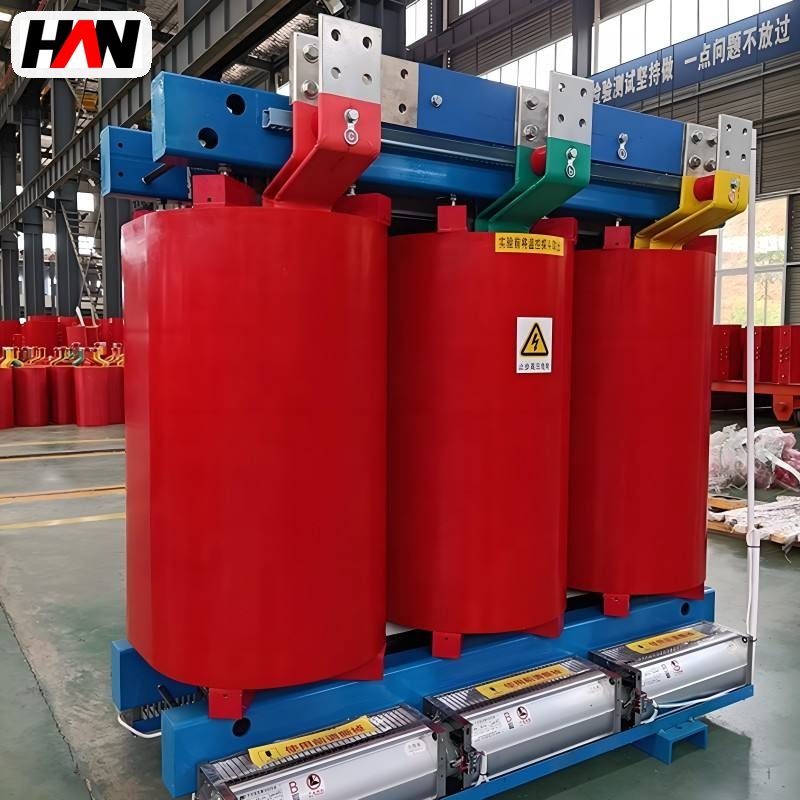
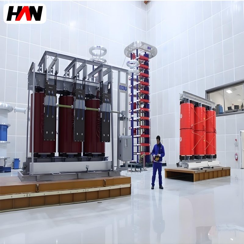
A cast resin dry-type transformer replaces the oil tank and the oil-soaked paper of a conventional unit with a solid epoxy casting formed directly around each winding. There is no liquid inside, so there is no oil level to watch, no spill bund to build, no oil sampling programme and no flammable pool sitting under the equipment. That one change is why these transformers end up in basements, cable tunnels, ships, hospitals, data halls and factory buildings where an oil-filled unit would need a fire-rated room of its own. The electrical duty is unchanged. Ratings run from 50 kVA to 2500 kVA, primary windings from 6 kV to 35 kV, secondaries at 400 or 415 V, with vector groups such as Dyn11 for a mixed three-phase and neutral load. What changes is how the heat leaves the winding and how much overload the unit will tolerate before the insulation gives up years of life. This page explains the construction, the numbers on the rating plate, the cooling options, and the cases where an oil-immersed transformer is still the better buy.
At a glance
| Rated power | 50 – 2500 kVA |
| Primary voltage | 6 / 10 / 15 / 20 / 35 kV |
| Secondary voltage | 400 / 415 V, others on request |
| Vector group | Dyn11 standard, Yd11 or Yyn0 optional |
| Insulation class | F (155 °C) or H (180 °C) |
| Cooling | AN natural, AF with fans |
| Short-circuit impedance | 4 – 6 % typical at 1000 kVA and below |
| Degree of protection | IP00 open, IP21 to IP54 enclosed |
| Design standard | IEC 60076-11 |
Reading the code and the family it belongs to
The familiar SCB designation is built from letters that each carry a meaning. The S marks a three-phase unit. The C marks a winding encapsulated in cast resin rather than wound dry and impregnated with varnish. The B marks a foil-type low-voltage winding, formed from wide aluminium or copper sheet rather than round wire. The number that follows, as in SCB10 or SCB11, is a loss-level code from the design series, not a power rating and not a voltage class. Two units of the same frame size can carry different numbers and differ mainly in no-load and load loss.
Inside the IEC framework the governing document is IEC 60076-11, the part of the power transformer series that deals with dry-type units. It sits alongside IEC 60076-1 for general requirements, IEC 60076-2 for temperature rise in oil-filled units, IEC 60076-3 for insulation levels and dielectric testing, and IEC 60076-5 for the ability to withstand a short circuit. Part 11 adds what the others cannot cover: how a solid insulation system is classified, how it is tested, and what its behaviour is in a fire.
That classification is worth learning because it appears in every serious enquiry. Climate class C1 or C2 covers operation down to minus 5 °C or minus 25 °C. Environmental class E0, E1 or E2 covers condensation and pollution, with E2 the demanding case for high humidity and frequent condensation cycles. Fire behaviour class F0 or F1 describes the contribution the unit makes to a fire, and F1 is the limited-hazard class that specifiers ask for in occupied buildings and underground rooms. A transformer described only as cast resin, with no class letters attached, has not told you much.
How the winding, the core and the casting fit together
The magnetic circuit is a laminated core of grain-oriented silicon steel, mitred at the corners and stacked in a three-limb arrangement for a three-phase unit. The core carries the flux; everything else exists to link current to that flux efficiently and to keep the heat it produces inside a manageable temperature. Yokes and limbs are clamped with insulated bolts and bands so that the structure does not resonate, because a loose core is a noisy core.
The low-voltage winding is usually a foil coil: a wide sheet wound layer on layer with a thin insulating film between turns. Foil has an advantage that is easy to miss. A wide, thin conductor shares current across its full width, so the axial flux that produces eddy losses in a wire-wound coil is far smaller, and the winding stays cooler at the same current density. Foil also gives the coil a stiff, self-supporting shape, which helps when the unit has to ride through a short circuit.
The high-voltage winding is wound as a layer or disc coil around the low-voltage coil, with spacers forming cooling ducts, and then placed in a mould and filled with degassed epoxy under vacuum. Vacuum is not a formality here. Any air pocket left inside the casting becomes a place where the electric field concentrates, and a cavity is exactly where partial discharge starts. The filled mould is cured on a controlled temperature profile so the resin cross-links fully and the casting does not shrink away from the conductor. Coils are then given a conductive screen on the outer and inner surface to smooth the field at the ends, where the winding leaves the casting.
The numbers on the plate, and what each one decides
A quotation for a dry-type transformer is a short list of figures. Most of them constrain something physical, and a few are only marketing decoration.
| Parameter | Typical value | What it constrains |
|---|---|---|
| Rated power, S | 50 – 2500 kVA | Continuous apparent power at the declared cooling stage |
| Highest voltage for equipment, Um | 7.2 – 40.5 kV | Clearances, creepage and the dielectric test level |
| Rated insulation level | Per IEC 60076-3 for the Um | Lightning impulse and power-frequency withstand |
| Vector group | Dyn11, Yyn0, Yd11 | Phase shift, earth-fault path and parallel operation |
| Short-circuit impedance | 4 % small, 6 % large | Fault current downstream and voltage dip on load steps |
| No-load loss | Set by the loss-level series | Energy cost of running the unit idle, all year |
| Load loss at 120 °C | Declared reference temperature | Heat released inside the enclosure at full load |
| Insulation class | F (155 °C) / H (180 °C) | Permitted winding temperature rise and service life |
| Winding temperature rise | 100 K class F, 125 K class H | How much copper is needed for a given loss budget |
| Cooling stage | AN, AN/AF | Capacity with and without fans running |
| Partial discharge level | 10 pC usual ceiling | Quality of the casting and the vacuum process |
| Degree of protection | IP00 – IP54 | Touch safety, dust, water and cooling airflow |
| Ambient and altitude basis | 40 °C, 1000 m | Whether the nameplate rating survives the real room |
Two of these deserve a sentence each. The impedance figure is a design choice, not a fixed property. A low impedance keeps the secondary voltage steady when a large motor starts, but it lets a harder fault current reach the downstream switchboard, which then has to be rated for it. A high impedance does the opposite. Most 6 kV to 35 kV cast resin units land between 4 % and 6 %, rising with rating because a larger unit has more leakage flux between windings.
The loss figures also need a reference temperature to mean anything. Load loss is normally declared at 120 °C for a class F unit, because copper resistance rises with temperature and a figure quoted cold would flatter the design. Comparing two quotations where one states load loss at 75 °C and the other at 120 °C compares nothing at all.
Engineering note. A dry-type transformer is not rated at 40 °C ambient for ever. IEC 60076-11 sets the reference at a maximum ambient of 40 °C and an altitude of 1000 m, with the daily and yearly averages below that. Install the same unit in an unventilated plant room that reaches 50 °C in August and the permissible temperature rise is used up before the load arrives. Either derate the unit, add mechanical ventilation to the room, or accept a shorter insulation life. Fans do not fix a hot room; they only move the same hot air faster.
Heat, insulation life and the honest limits of a dry design
Cast resin removes the oil, not the heat. Every watt of loss still has to leave the winding by conduction through the casting, then by convection from the coil surface to the air, then out of the enclosure. Air is a poor heat carrier compared with oil, roughly a factor of ten worse in volumetric heat capacity, so a dry transformer needs wider ducts, more surface and a bigger box for the same rating. That is the physical reason a 1600 kVA dry unit is physically larger than an oil unit of the same rating.
Insulation life is a function of temperature, and the relationship is brutal. Solid insulation ages by a chemical reaction that roughly doubles in rate for every 6 to 8 K above its rated hotspot, with 8 K the figure most often quoted for the older class A systems. Run a class F winding at 155 °C hotspot continuously and it is inside its design life. Run it at 170 °C and the same insulation may last a quarter as long. Nothing fails on the day; the unit simply reaches the end of its life earlier, which is why temperature-rise records matter more than a catalogue efficiency claim.
The cooling designation states exactly what the rating assumes. AN means natural circulation of air: convection only, no moving parts, quiet and maintenance-free. AN/AF means the unit has fans that switch on at a set winding temperature and lift the rating by pushing more air through the ducts. A typical boost is 25 % to 40 %, and it must be declared as a separate rating with its own current, because the AF figure is not available when a fan fails. Protection should start the fans early and alarm on fan failure, not wait for the winding to reach its limit.
Partial discharge is the second slow failure mode. A cavity, a delamination or a sharp conductor edge inside the casting concentrates field until the air in the void breaks down, and each small discharge erodes the resin a little further. That is why the vacuum casting process, the curing profile and the routine discharge measurement belong together in one quality chain. A unit measured at 5 pC on the shop floor is not automatically a good unit for twenty years, but a unit that cannot hold 10 pC will not get there.
Dry against oil-immersed, on the trade-offs that matter
Neither technology wins in general. The choice usually follows from the room, the fire policy and the load profile rather than from the transformer itself.
| Criterion | Cast resin dry type | Oil immersed |
|---|---|---|
| Fire and civil works | No oil pool, no bund, F1 class available | Bund, fire wall and separation distances usually required |
| Purchase cost at equal rating | Higher, more copper and more labour | Lower for the transformer alone |
| Short-time overload | Limited: little thermal mass to absorb a surge | Oil carries heat away and gives thermal inertia |
| Audible noise at equal rating | Usually higher: the tank of an oil unit damps core noise | Lower, and easier to shield |
| Maintenance routine | Dust removal, fan and thermostat checks, torque checks | Oil tests, gasket and breather care, tap changer service |
| Footprint in a building | Larger unit, but no clearances to neighbours | Compact unit inside a larger fire-rated room |
| Best fit | Indoor, underground, occupied buildings, clean processes | Outdoor yards, heavy cyclic load, tight budget |
The overload row is the one that catches people out. Oil has a large thermal capacity and circulates by itself, so an oil unit can carry a substantial emergency overload for an hour without the winding hotspot climbing far. A cast resin winding has very little mass relative to its losses and no self-circulation, so its hotspot responds within minutes. If the duty includes regular motor starting, welding load or a batch process with a heavy peak, the dry unit has to be sized for the peak, not for the average.
Where it sits in the distribution chain
In a typical arrangement the medium-voltage ring main or a load-break tee feeds a fused or vacuum circuit breaker, which feeds the transformer primary. The secondary lands on a main incoming breaker inside a low-voltage switchboard, and from there the plant is distributed. Because the dry unit is often installed inside the building it serves, the cable run on the low-voltage side is short, which is worth real money in copper at 2500 A and above.
The load types that suit the technology share one property: they are predictable and they stay inside the building. Lighting and small power in a tower or a shopping centre, HVAC plant in a basement, traction and signalling rooms, water treatment works, hospital theatres and imaging suites, semiconductor and pharmaceutical clean rooms where an oil leak would be a contamination event, and marine or offshore rooms where a fuel fire is the last thing anyone wants. Solar and battery plants use dry units indoors on the inverter side for the same reason.
Two placement questions come up early. The first is ventilation: a dry transformer releases all its losses into the room, so the room needs an air path with a low inlet and a high outlet, sized for the loss figure at the ambient you actually expect. The second is the enclosure. An open IP00 unit needs a fenced cell or a locked room; an IP21 to IP23 unit with top covers protects against dropped objects and vertical drips; a fully enclosed IP54 unit solves the environment problem at the cost of cooling, and needs its own airflow design.
Specification and commissioning checklist
- Write the ambient into the specification. Maximum summer room temperature, altitude and whether the plant room has mechanical ventilation decide the real rating more than the kVA figure does.
- State the cooling basis of every rating. Ask for the AN figure and the AF figure separately, with the fan control temperature and the alarm contact details.
- Fix the vector group before ordering. Dyn11 gives a neutral for single-phase loads and blocks zero-sequence from the primary. Change it later and every downstream protection setting changes with it.
- Ask for the class letters. Climate, environmental and fire class in the enquiry, so that C2, E2 and F1 are either offered or excluded in writing.
- Require the discharge figure with its test voltage. A number without the voltage at which it was measured cannot be compared between suppliers.
- Plan the cable and busbar interfaces. Terminal arrangement, phase spacing and the room for large lugs are fixed at design, not on site.
- Agree the site routine checks. Insulation resistance on each winding, ratio and polarity, winding resistance, a visual check for casting damage on transport, and a fan and thermostat function test.
Frequently asked questions
Why is a dry-type transformer usually more expensive than an oil unit of the same rating?
Because the insulation system costs more and the design needs more active material. Epoxy, vacuum casting, curing and discharge testing are expensive processes, and air cooling is less effective than oil, so the winding needs more copper and a larger core to hit the same loss target. The saving appears later, in the building: no bund, no fire wall, no oil handling.
Does a cast resin transformer need maintenance?
Less than an oil unit, but not none. The coils should be cleaned of dust, because a dust layer on a casting insulates the surface and pushes the winding temperature up. Fans, thermostats and winding temperature sensors need a functional test, and terminal torque should be checked at the first service and periodically after that.
Can it be installed outdoors?
Not as an open unit. Cast resin coils tolerate moisture far better than paper insulation, but the enclosure, terminals and accessories do not. An outdoor installation needs an enclosure rated for the site, typically IP54 stainless steel, with a sunshade and a designed air path. The transformer inside is the same; the weather protection is a separate engineering problem.
What does the F or H class actually permit?
The class sets the maximum hotspot temperature the insulation system is designed for: 155 °C for class F and 180 °C for class H. The permitted average winding rise over a 40 °C ambient is lower than that, around 100 K for class F and 125 K for class H, because the hotspot inside the winding runs hotter than the measured average.
Is a higher impedance always better for the switchboard?
It reduces the fault current the low-voltage board has to interrupt, which can save money downstream. It also increases the voltage drop when a large load starts and increases reactive losses in normal operation. The right figure comes from a short-circuit study, not from a preference.
How is capacity affected above 1000 m altitude?
Air density falls with height, so both cooling and dielectric strength degrade. IEC 60076-11 requires the altitude to be declared, and a unit specified for 1000 m needs either a derated rating or larger clearances for a higher site. The correction is not a single percentage; it is applied to the temperature rise and to the insulation coordination separately.
Ratings, vector group, cooling stage, enclosure and terminal layout are set per project, so a cast resin unit is built to the room it will sit in rather than chosen from a list. Send the load schedule, the supply voltage and the plant room conditions and the specification can be fixed from those three documents.