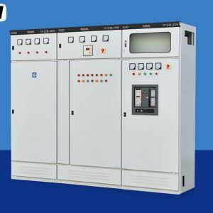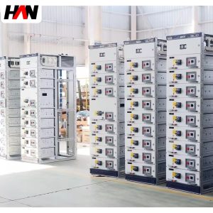
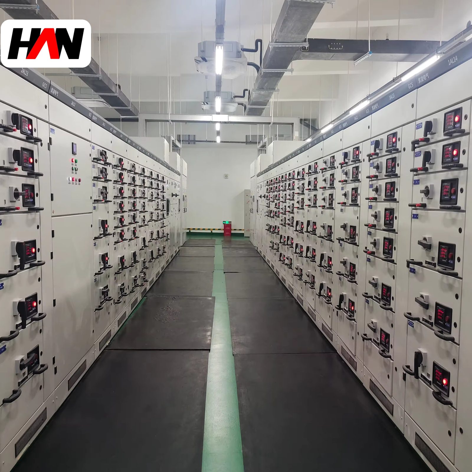
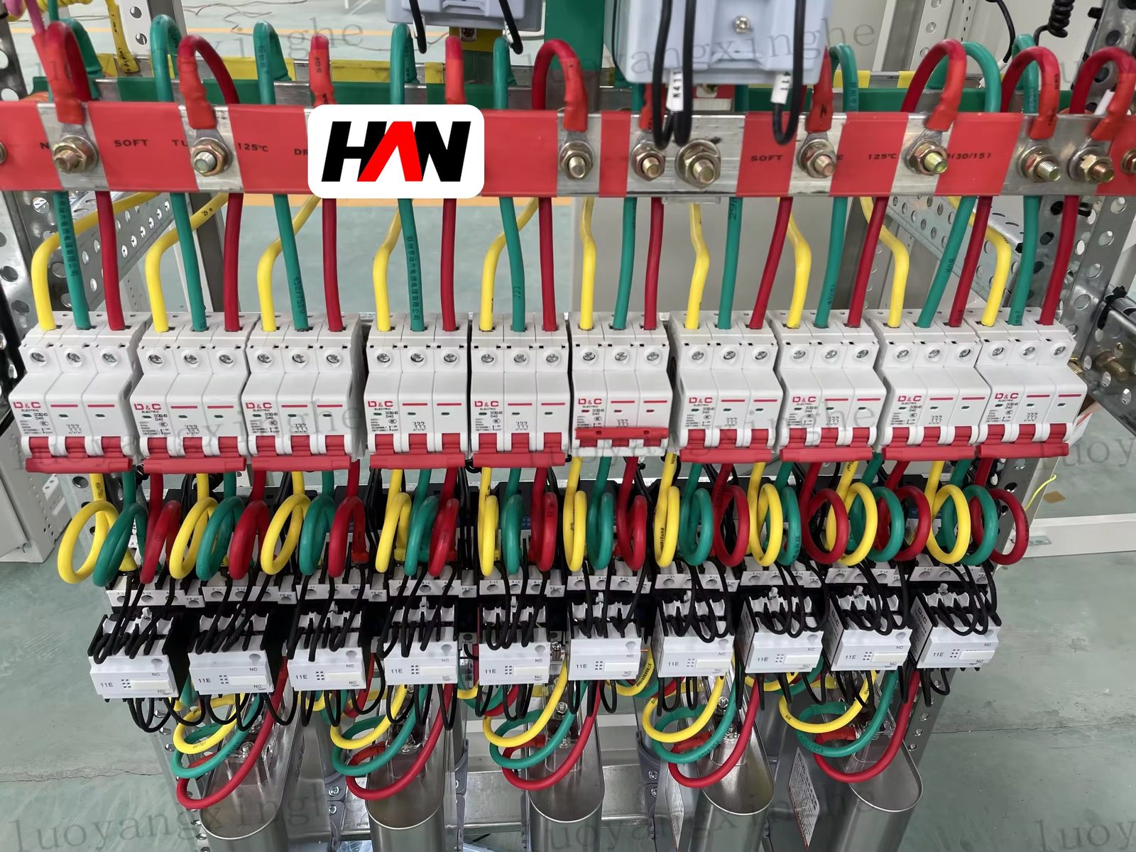
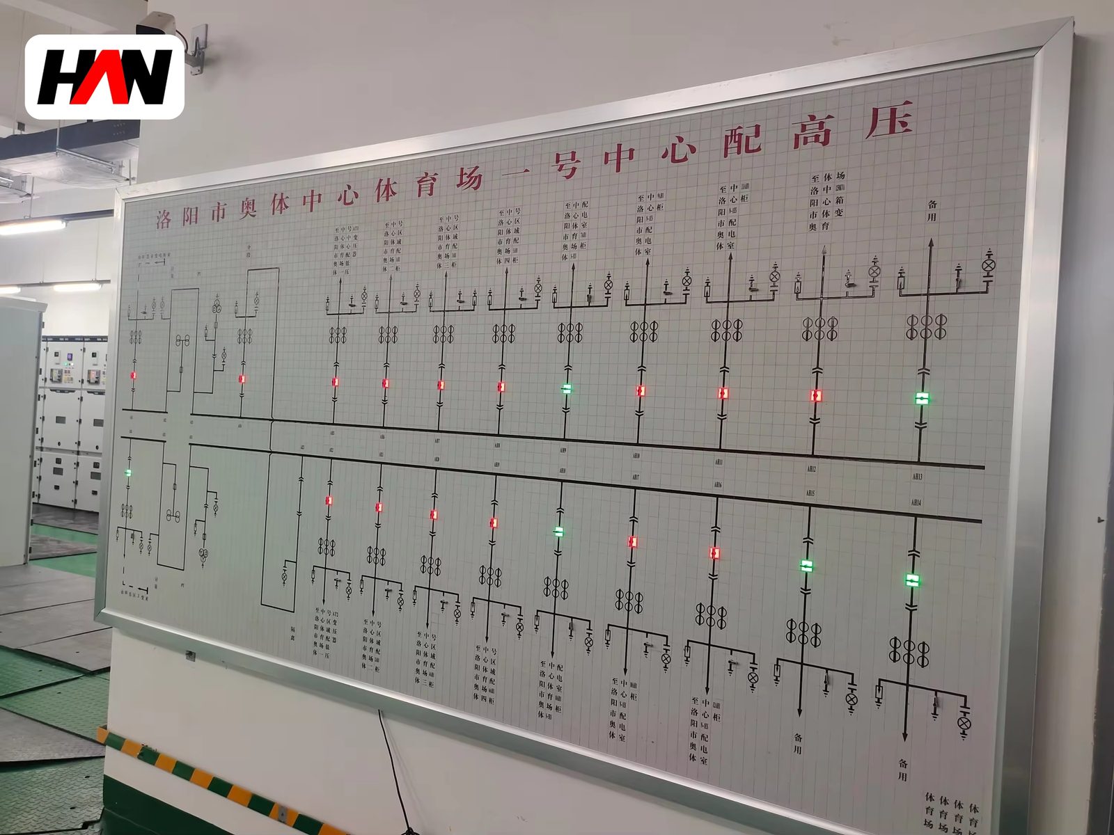
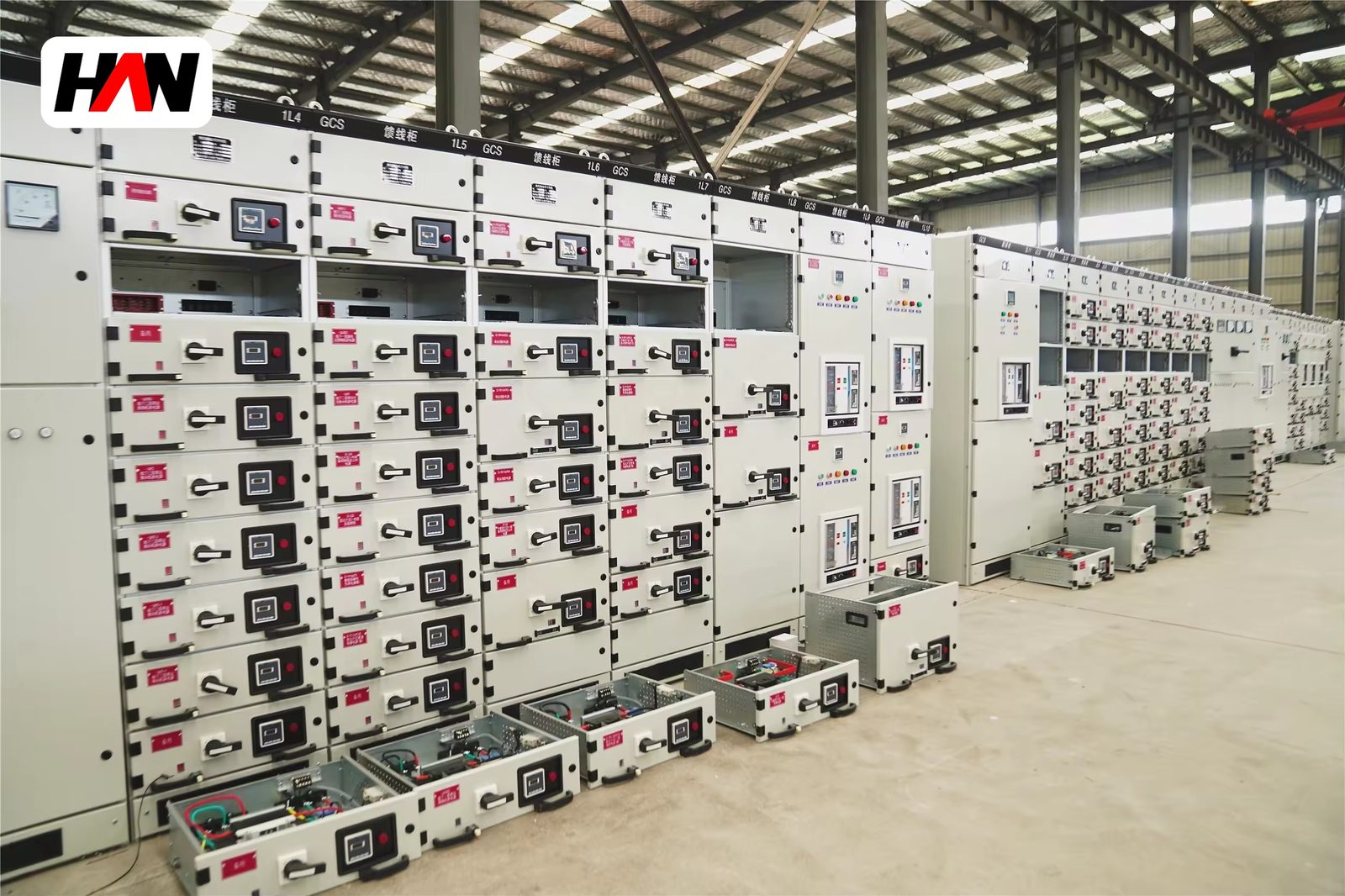
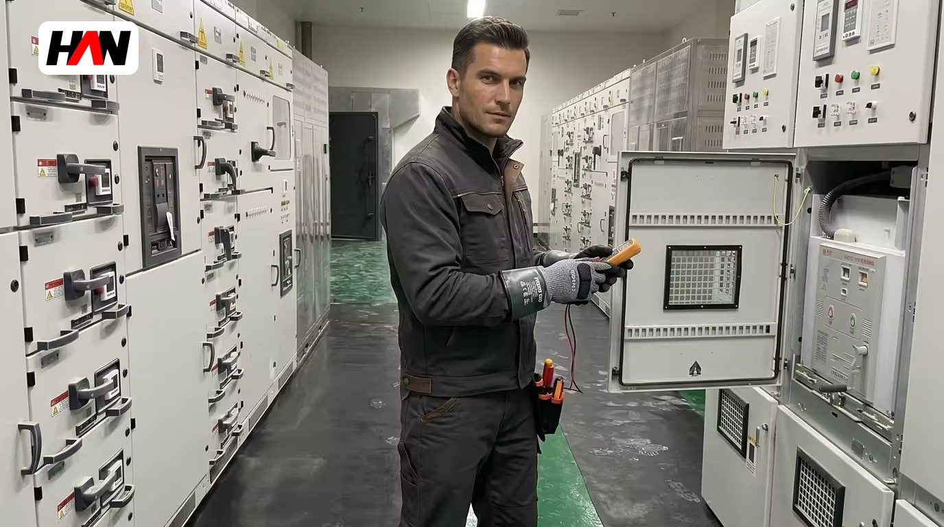
A GCK assembly is a low-voltage motor control centre built around withdrawable feeder units, each one a complete starting chain rather than a single breaker. Inside a unit that is 200 mm or 400 mm high sit the short-circuit protective device, the contactor, the overload protection and the terminals, wired and tested as a set. That packaging is the point: a motor feeder fails as a system, and a system that can be withdrawn and replaced in minutes keeps a production line running. This page covers what the GCK and GCD designations describe, how a feeder chain is protected and coordinated to IEC 60947-4-1, what happens thermally when soft starters and drives are built in, and how the choice between this family and a general draw-out distribution board actually gets made.
At a glance
| Rated operational voltage | 400 / 690 V AC |
| Main busbar current | up to 4 000 A |
| Short-time withstand, Icw | 50 kA, 1 s |
| Motor feeder range | 0.37 – 250 kW typical |
| Utilisation category | AC-3 per IEC 60947-4-1 |
| Unit heights | 8E, 16E, 24E |
| Internal separation | Form 3b or 4 |
| Degree of protection | IP30 – IP54 |
| Design standard | IEC 61439-1 and 61439-2 |
What the designation covers
GCK and GCD belong to the same regional naming habit as other three-letter low-voltage codes: they mark a family of withdrawable motor control assemblies, with variations in unit size and in whether part of the board is fixed. The letters are not an international performance class, and they say nothing about fault level. GCD is usually the variant with a mixed layout, where large or special feeders occupy fixed compartments while the ordinary starters sit in drawers.
Under IEC 61439 the board is a power switchgear and controlgear assembly verified to Part 2, with Part 1 supplying the general rules on temperature rise, short-circuit withstand, clearances, protective bonding and the division of verification between the original manufacturer and the assembly builder. The motor starters inside it are components verified to IEC 60947-4-1, and that second standard is where the interesting engineering lives, because a contactor is not a switch and an overload relay is not a breaker.
A feeder is a chain, not a device
The devices divide the work. The breaker or fused switch-disconnector interrupts short-circuit current and provides isolation. The contactor makes and breaks the running current and, in a normal start, the starting current. The overload relay watches the current the motor actually draws and trips on a thermal model rather than on a magnetic threshold. Asking one device to do all three jobs is how feeders get destroyed: a moulded-case breaker alone will happily carry a locked-rotor current for long enough to burn a winding, and an overload relay alone has no breaking capacity worth mentioning.
The reason the chain lives in one drawer is mechanical, not electrical. Each unit is wired and tested complete, with the contactor coil circuit, the auxiliary contacts and the terminal blocks where the field cable lands. Swap the unit and the whole chain is renewed at once, including the parts that were about to fail next.
Ratings and what they control
| Parameter | Typical value | What it controls |
|---|---|---|
| Rated operational voltage, Ue | 400 / 690 V | Starter insulation and coil voltage choice |
| Rated insulation voltage, Ui | 690 / 1 000 V | Clearance inside a densely packed drawer |
| Main busbar current | up to 4 000 A | Transformer capacity and section count |
| Rated short-time withstand, Icw | 50 kA, 1 s | Fault level at the board terminals |
| Rated peak withstand, Ipk | 2.1 × Icw at 50 Hz | Forces on bars and on unit contacts |
| Utilisation category | AC-3, AC-1 for distribution | Contactor size for the same motor rating |
| Overload trip class | 10, 20 or 30 | Trip time from cold, matched to starting time |
| Coordination type | Type 1 or Type 2 | What survives a downstream short circuit |
| Form of internal separation | 3b or 4 | Working on one feeder with the busbar live |
| Degree of protection | IP30 – IP54 | Dust, water and cooling air, per IEC 60529 |
| Ambient temperature | −5 to +40 °C | Contactor and relay derating in a hot room |
| Unit height | 8E, 16E, 24E | Room for a drive, a soft starter or a large contactor |
50 kA for one second and 4 000 A of busbar are assembly figures. What limits a motor control centre in practice is usually neither: it is the temperature inside a drawer that holds a contactor, a relay and a set of terminals in a space the size of a shoebox. IEC 61439-1 measures that as a temperature rise above ambient at the terminals and at accessible surfaces, and the result depends as much on how many neighbouring units are loaded as on the device itself.
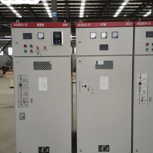
Engineering note. Motor control centres are low-voltage assemblies, with Ue at 690 V or below. A page that advertises one at 6 kV, 12 kV or 24 kV is describing medium-voltage switchgear to IEC 62271-200, which interrupts fault current in a vacuum bottle or a gas chamber and controls a motor through a contactor or a circuit-breaker in a very different enclosure. The voltage class decides the product family before any other parameter is discussed.
Protection and coordination: where motors differ from cables
A cable has one thermal limit and an overload relay protects it easily. A motor has two: it must be allowed to draw five to seven times its rated current during a start, and it must be protected against a sustained overload that would cook the winding. IEC 60947-4-1 handles this with trip classes. Class 10 trips within a defined time from a cold start and suits pumps and fans that accelerate in seconds. Class 20 and class 30 stretch the permissible starting time for high-inertia loads such as crushers, centrifuges and long conveyors. Set a class 10 relay on a load that needs twelve seconds to accelerate and the plant will trip on every start.
Coordination is the other half. Type 1 coordination accepts damage to the contactor or relay after a short circuit, provided the fault is cleared and the assembly remains safe; the damaged parts are replaced. Type 2 requires the same components to remain usable afterwards, with only light contact welding permitted and no damage to the overload relay. Type 2 costs more because it constrains the combination of breaker and contactor, and it is worth the money where a spare unit may be far away. The declaration belongs to the tested combination, not to each device taken alone.
Utilisation category sits underneath all of this. A contactor rated for AC-1 carries a resistive load and can be smaller; in AC-3 it must make the starting current and break the running current of a squirrel-cage motor, which cuts its rating on the same frame substantially. Two boards with the same motor list can therefore differ in contactor size, and only the one specified in AC-3 is honest about motor duty.
Soft starters and drives inside a drawer
A soft starter is mostly thyristors and heatsink, and its losses land inside the enclosure. A drive adds a rectifier, a direct-current link and an inverter, and it delivers two problems at once: more heat per ampere, and harmonic current that flows back into the busbar. Both need space that a standard 8E starter pocket does not have, which is why drive units are usually 16E or 24E and often occupy their own column with dedicated ventilation.
Harmonics matter for the whole board, not just the drive. Distorted current raises the root-mean-square value for the same useful power, so busbars, transformers and neutral conductors heat up more than the load list suggests. IEC 61439 assemblies are verified with a declared harmonic content in mind, and a board retrofitted with several drives can end up running hotter than the design assumed. The remedies are engineering, not paperwork: line reactors or filters, a separate drive column, and shielded motor cables with the screen bonded at both ends to keep high-frequency noise out of control wiring.
Where drives are expected later, the cheapest decision is space. A column ordered empty, with its busbar and shutters fitted and a ventilation path reserved, costs a fraction of rebuilding a board in service, and it keeps the drive heat away from the starters that share the section.
Choose the control centre or the distribution board
| Question | Motor control centre | Draw-out distribution board |
|---|---|---|
| Typical outgoing circuit | Starter with contactor and overload | Breaker feeding a board or a panel |
| Circuit count | High, often dozens of small units | Moderate, larger feeders |
| Control wiring | Extensive: coils, interlocks, signals, communications | Minimal |
| Maintenance skill | Motor and drive competence on site | Protection settings and cable work |
| Cost driver | Number of units and their control content | Busbar current and fault level |
In a process plant with a long line of conveyors, the choice is obvious: dozens of small, repetitive starters with local control and frequent stopping. In a building or a workshop where the board mainly splits power into sub-boards, the distribution design is cheaper and simpler. Many plants end up with both in the same electrical room, sharing a busbar through a section joint.
Selection and commissioning checklist
- Ask for tested combinations. The breaker, contactor and relay combination should come with a declared coordination type and a rated conditional short-circuit current, not just individual device certificates.
- Match the trip class to the load. Get the acceleration time for each high-inertia drive from the mechanical supplier before the relay is set.
- Count the control cores early. Two-wire and three-wire control, run and trip signals, analogue feedback and a communications bus all consume terminal space inside the unit.
- Reserve space for drives. Ventilated columns with shutters fitted are far cheaper at build time than a retrofit in a live plant.
- Agree the harmonic assumption. If several drives will share the busbar, say so, because it affects both the temperature rise and the protection settings.
- Test every unit before it leaves. Insulation resistance, a functional start-stop run with the contactor, a simulated overload trip and a check of the mechanical interlock take minutes in the works and save days on site.
Frequently asked questions
Is a motor control centre the same as a distribution board?
No. Both are low-voltage assemblies, but the control centre is organised around starters with contactors, overload protection and control circuits, while a distribution board splits power through breakers. The switchgear standards overlap; the engineering content does not.
Why does a contactor have two different current ratings?
Because the duty differs. In AC-1 the load is resistive and easy to break; in AC-3 the contactor must make the starting current of a motor and break the running current repeatedly. The same frame carries less current in AC-3, and that is the figure to use for motor feeders.
Can a variable speed drive be fitted in a standard starter pocket?
Rarely. A drive needs more height, more ventilation and often a separate cable route for the motor cable. A 16E or 24E unit with its own airflow path is the practical arrangement, and a dedicated column is better still.
What does Type 2 coordination protect?
The components themselves. After a short circuit, the contactor and overload relay must remain serviceable, with only light contact welding allowed. Type 1 accepts replacement of damaged parts instead, which is cheaper to declare and more expensive to operate.
How is a motor feeder isolated for maintenance?
By withdrawing the unit to the disconnected position, where the fixed contacts are covered by shutters and the drawer can be padlocked, or by opening an upstream device and locking it off. The correct method is the one written in the site procedure for that board and that permit.
Unit schedule, starter types, fault level and the space reserved for drives are decided per project, so the section layout is built from the motor list and the single-line diagram. Send both and the arrangement can be confirmed before fabrication.