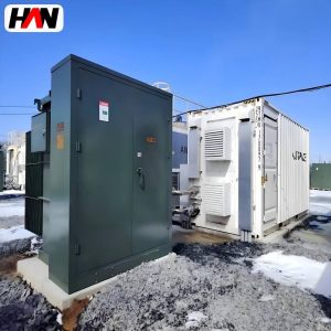
A ZGS11 unit is a distribution transformer that has been given a metal box, a lock and a place on the pavement. The transformer inside is an ordinary three-phase oil-immersed machine; what makes the product is the arrangement around it. High-voltage cables arrive underground, terminate in elbow connectors on bushings that are insulated down to their surfaces, pass through fuses that sit in oil-filled wells, and meet a tap plate that can be set to five positions before the unit is energised. The low-voltage side leaves through a separate compartment. Everything an operator might touch is either dead or covered, and everything a vandal might reach needs a tool. That combination is why this construction dominates underground residential and commercial distribution in North American practice, and why it has been adopted in dense Asian and Middle Eastern networks where overhead lines are not acceptable. This page explains the design logic, the ratings that matter, the heat problem created by the box, and the installation constraints that decide whether a unit fits on a given plot.
At a glance
| Rated power | 100 – 5 000 kVA |
| High-voltage class | 10 / 20 / 35 kV |
| Low-voltage | 0.4 kV, or 480Y/277 V for ANSI networks |
| Cooling | ONAN, self-cooled inside the enclosure |
| High-voltage termination | Dead-front bushings with separable elbows |
| Protection | Insert-type current-limiting fuses in wells |
| Taps | Five positions, ± 2 × 2.5 %, off-circuit |
| Enclosure | Welded, gasketed, lockable, tamper-resistant |
| Reference standard | IEEE C57.12.34, IEC 60076 |
What the designation and the format describe
In the naming used by a large part of the Asian manufacturing base, the letters mark a three-phase combined substation of the American box type and the digits mark the transformer design generation, following the same convention as an S-series unit. The word “combined” is the important part: the product is not just a transformer in a weatherproof shell, it is a switch, a fuse, a transformer and a low-voltage terminal brought together in one enclosure that arrives on site complete.
Two design traditions produce a similar-looking box and behave differently. The European kiosk substation is a walk-in or bolt-on enclosure, often with a ring main unit in one compartment and a dry-type or oil-immersed transformer in another, built to IEC 62271-202 for the assembly and IEC 60076 for the transformer. The American pad-mounted unit compresses the same functions into a much lower, sealed body with no walk-in space, and it is specified through IEEE C57.12.34, the standard for three-phase pad-mounted compartmental-type self-cooled distribution transformers. The ZGS11 format follows the second tradition, with the voltage and frequency adapted to the network it serves.
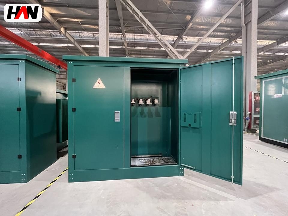
The result is a footprint measured in a fraction of a square metre rather than a small room, no accessible interior, and a service routine that is performed from outside with a hotstick rather than from inside with a toolbox. Whether that is better depends on where the unit has to stand. A campus with spare land and a maintenance team prefers the kiosk. A city street with a two-metre strip between the kerb and the property line has no such option.
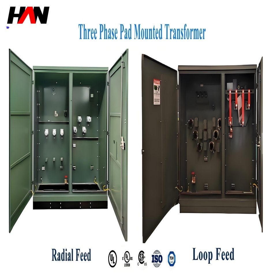
The three compartments and what sits inside them
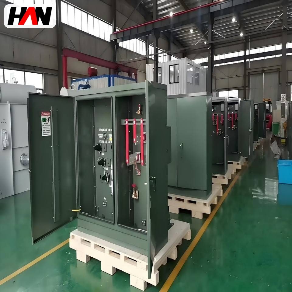
A pad-mounted unit is divided by steel barriers into a high-voltage compartment, a transformer compartment and a low-voltage compartment. The barriers are not decoration. They let a crew open one compartment while the other two remain closed, and they stop a fault in one from spreading directly into the next.
The high-voltage compartment holds the bushings. They are dead-front in the literal sense: the conducting part is buried inside an epoxy or rubber moulding, and only an insulated surface is exposed when the elbow connector is pulled. Cable is terminated in a separable elbow that pushes onto the bushing and is held by a bail, so a crew can isolate a cable without opening the transformer. That single detail explains much of the format’s popularity: there is no exposed live metal at the point where a person with a hotstick stands.
Protection is by insert-type current-limiting fuses held in wells that are part of the transformer’s oil volume or bolted to the tank. The fuse element sits in a holder that can be inserted or withdrawn from outside with a stick, which means a blown fuse is replaced without draining oil or opening the tank. Because the fuse is current-limiting, it cuts a high fault current off in the first quarter cycle, before the peak, and that lets the transformer and the cables be protected against a fault level they could not withstand thermally.
The transformer compartment holds the core, windings and oil, with the tap plate on the high-voltage side. Five positions give a range of plus or minus five percent in two steps of 2.5 percent, and the plate is set before energisation with the unit isolated. The low-voltage compartment contains the secondary bars, the neutral terminal, and space for metering or a main breaker depending on the specification. Cable entry is from below, through a removable plate, which allows the pad to be poured first and the unit landed afterwards.
The winding connection deserves a word, because it decides how the low-voltage side behaves under unbalanced load. Units for ANSI networks are typically delta on the high-voltage side and star with a brought-out neutral on the low-voltage side, written as a 30 degree displacement between the two. The delta primary gives zero-sequence current somewhere to circulate without escaping into the feeder, which keeps triplen harmonics out of the network; the secondary neutral gives single-phase loads a return path and gives an earth fault enough current for protection to see it. A unit delivered with an ungrounded star point looks identical from outside and behaves completely differently the first time a phase-to-earth fault occurs.
Ratings, and what each figure governs
The range runs from 100 kVA, where a single unit serves a small block, to 5 000 kVA, where the same enclosure becomes a small substation feeding an industrial plant or a data hall. Impedance, fuse rating and enclosure size all shift across that span.
| Parameter | Typical value | What it governs |
|---|---|---|
| Rated power | 100 – 5 000 kVA | Secondary current, enclosure volume and shipping mass |
| High-voltage class | 10 / 20 / 35 kV | Bushing length and the clearance the compartment must keep |
| Impulse level | Per system voltage, e.g. 95 kV class at 15 kV | Insulation thickness in the winding ends and bushing design |
| Feed arrangement | Radial or loop, two to six bushings | Switching positions and whether the unit can be by-passed |
| Short-circuit impedance | Low single figures to around 6 % | Secondary fault current and the LV equipment rating needed |
| Fuse rating and speed | Chosen from the transformer’s full-load current | Coordination with upstream protection and through-fault survival |
| Taps | Five positions, ± 2 × 2.5 % | Secondary voltage on a feeder that sits high or low |
| Temperature rise | 65 K average winding, 60 K top oil | How much heat the enclosure must vent without recirculating it |
| Enclosure finish | Galvanised or coated steel, gasketed | Corrosion life, and whether water reaches the bushings |
| Degree of protection | IP54 typical for the LV compartment | Dust and hose ingress per IEC 60529 |
| Sound level | Declared per rating, measured at distance | Distance to a bedroom window or a quiet zone boundary |
The power figure needs the same plain reading it needs anywhere else. Kilovolt-amperes are apparent power, and a 1 000 kVA unit feeding a load at 0.9 power factor delivers 900 kW of useful work while carrying the full 1 000 kVA of current through its windings. Megavolt-amperes are simply a thousand of those, so 5 000 kVA and 5 MVA describe the same unit — a fact worth remembering when a specification mixes both units in one line and appears to describe two different products.
Engineering note. The pad-mounted standard most utilities cite was written around the distribution range, and a 5 000 kVA unit sits above that range. In practice this means the enclosure and compartment rules are still applied as the reference, while the transformer itself is specified against the general requirements and, where relevant, the distribution substation documents. A 5 000 kVA unit also changes the electrical picture: fault current at the secondary terminals is high enough that the low-voltage switchboard, not the transformer, becomes the deciding purchase. Confirm the secondary fault level before fixing the impedance.
Heat, sound and the cost of a sealed box
Putting a transformer inside an enclosure changes its thermal environment three ways. The box blocks wind, so the convective path that a free-standing unit relies on is weakened. It radiates heat back from its own sunlit surface. And it traps a layer of hot air around the tank, so the air the radiators see is warmer than the ambient the rating assumes. Enclosure design answers with louvres placed low on the inlet and high on the outlet, baffled so that rain cannot follow the air path, and with a gap between the tank and the wall wide enough for a natural circulation loop. A pad-mounted unit is tested as an assembly, so the declared rating reflects the enclosure rather than the bare transformer.
Sound follows the same physics as the losses. Magnetostriction makes the core change dimension very slightly twice per cycle, so the fundamental noise sits at twice the supply frequency — 100 Hz on a 50 Hz network, 120 Hz on 60 Hz — with harmonics above it. The tank walls behave like a diaphragm and radiate that vibration. Inside an enclosure the sound reflects off the panels, and a light gauge cover can rattle in sympathy, which is why enclosure panels are stiffened and why some units are specified with a sound level rather than a core flux limit. Distance is the cheapest attenuator; a unit placed two metres from a bedroom window needs a lower declared level than one on a kerb.
Temperature rise is expressed in kelvin above ambient because the absolute temperatures depend on where the unit stands. IEC 60076-2 limits a naturally cooled oil-immersed unit to 60 K top-oil rise and 65 K average winding rise, with an allowance for the hot spot above that. What those limits protect is paper insulation, which ages by a chemical reaction that speeds up as temperature climbs; the rule of thumb used across the industry says the rate doubles for each additional 6 K at the hot spot. It is an approximation, not a clause in a standard, but it explains why a unit that runs at its limit every afternoon for twenty summers is not the same asset as one that idles at half load.
Heat is also the reason the enclosure cannot be made arbitrarily compact. Every reduction in surface area either raises the temperature rise or forces a lower kVA for the same footprint. When a site demands the smallest possible box, the honest answer is usually a lower-loss grade, which reduces the heat to be rejected in the first place, rather than a tighter enclosure around the same design.
Why the high-voltage side is built dead-front
Underground distribution brought a problem that overhead practice never had: the switching point sits at ground level, in public space, where anyone can walk up to it. A conventional live-front arrangement with exposed studs and bare jumpers would be an unacceptable risk in that position, and it would also fail in wet weather. The dead-front answer moves the conductive parts inside a solid insulation moulding and brings the cable in through a separable connector whose outside surface remains at earth potential when it is disconnected.
This is what allows the operating routine to be simple. A crew isolates a cable by pulling an elbow with a stick, verifies the dead condition at a test point built into the connector, and works on the cable. No compartment is opened to the air, no bushing is exposed, and the transformer stays sealed. It is also what makes vandal resistance practical: the enclosure can be locked with a single penta-head bolt, the hinges can be concealed, and the absence of exposed live parts means an opened panel does not immediately create an electrical hazard at reach height.
Engineering note. Fuse selection is a coordination exercise, not a lookup. The fuse has to carry the transformer’s rated current and its magnetising inrush without operating, clear a secondary fault before the tank is damaged, and still sit below the upstream device’s curve so that a fault trips the nearest protection first. A fuse chosen only to match full-load current often operates on energisation in cold weather, and a fuse chosen generously leaves the transformer exposed.
Comparing enclosure formats
| Criterion | Pad-mounted unit | Walk-in kiosk | Indoor vault |
|---|---|---|---|
| Footprint | Smallest, pavement scale | Room scale, needs a door and a path | Building volume, needs fire separation |
| Working access | From outside, with a stick | Walk in, tools and test gear at hand | Walk in, controlled environment |
| Cable termination | Separable elbows, underground | Cable boxes, glands, either direction | Cable tray or trench entry |
| Cooling | Louvred, convection only | Louvres or forced ventilation possible | Room ventilation, can be mechanical |
| Public exposure | High, so tamper resistance is compulsory | Moderate, depends on the fence line | Low, inside a building |
| Best fit | Streets, compounds, car parks, housing blocks | Industrial estates, campuses, utility yards | Basements, towers, plants with strict fire rules |
Fitting into a city street
The constraint that decides most urban installations is not electrical. It is the strip of ground available between the kerb and the property line, and the rules that govern what may stand on it. A pad-mounted unit needs a concrete pad, a clear working space in front of each door or panel, a cable trench or duct bank underneath, and enough separation from doors, windows and combustible material to satisfy the local code. Where that strip is narrow, the unit is set with its doors facing the roadway and the working clearance taken from the pavement, which in turn requires the pad to sit flush and the doors to swing without obstructing pedestrians.
Drainage matters as much as clearance. A pad that ponds water will eventually put the cable entry plate under standing water, and the gasket that was meant to keep it out becomes the path in. The pad is normally finished a little above the surrounding surface with a slope away from the unit. In areas with vehicle traffic, bollards protect the enclosure from impact, and in areas with a vandalism history the enclosure is specified with concealed hinges, a single locking point and a body that cannot be opened with common hand tools.
Dense networks also place several of these units close together, each feeding a block or a building. That pattern changes the protection philosophy: with a loop-feed arrangement, a fault on one cable section can be isolated and the healthy side back-fed, so a unit can be worked on without leaving customers dark. The radial version of the same enclosure cannot do that, which is why the feed arrangement is chosen at the network design stage and reflected in the bushing count and the switch fitted.
Selection and commissioning checklist
- Decide radial or loop before ordering. The bushing count, the switch and the fuse arrangement all follow from that single decision.
- Check the fault level at both ends. The fuse must clear a secondary fault, and the low-voltage board must survive the current the transformer can deliver.
- Set the taps against measured voltage. Five positions cover plus or minus five percent, which is enough for a feeder that drifts, but not for a network with a persistent voltage error.
- Confirm the cable interface. Elbow size, bushing interface type and cable insulation diameter have to match the cable being pulled, and the entry plate has to pass it.
- State the sound limit if people live nearby. A declared level at a stated distance is a specification item, and it is cheap to agree before production and expensive to fix after installation.
- Agree the finish for the atmosphere. Coastal air, road salt and industrial fumes each argue for a heavier coating system and stainless hardware.
- Plan the lift and the pad. Mass, lifting points, pad dimensions and the crane position are fixed by the enclosure size, and a mis-sized pad is the most common reason a delivery is refused.
Frequently asked questions
Can the unit be installed on a slab above a basement car park?
It can, if the structure is designed for the mass and the cable route is planned. What usually fails is drainage and access, not strength: water needs somewhere to go, and the working clearance in front of the doors has to exist at the final surface level.
What does the five-position tap actually give me?
Two steps of 2.5 percent above nominal, nominal, and two steps of 2.5 percent below, so roughly plus or minus five percent in total. It is set with the unit isolated, which is why it corrects a seasonal or permanent voltage offset rather than a daily swing.
Why is the low-voltage compartment separately barriered?
So that secondary work, metering or a cable replacement can be done with the high-voltage compartment closed and the transformer energised. The barrier is what makes that safe, and it also stops a low-voltage fault from reaching the high-voltage terminations.
Does a sealed enclosure remove the need for oil testing?
No. Seals age, gaskets take a set, and moisture finds its way in through the cable entry. Sampling the oil periodically is still the cheapest way to catch a winding problem before it becomes a failure.
How close can it stand to a building?
That distance is set by local fire and electrical code, and it depends on whether the wall is rated, whether there are openings, and how the unit is protected. Treat the code figure as a minimum and add working clearance for the doors.
Rating, feed arrangement, bushing count, fuse class, compartment layout and finish are all fixed per order, so the enclosure can be matched to a specific pad and network rather than to a standard drawing. Send the site plan and the network fault level and the configuration can be settled from those two documents.